Pioneer PDP-5070HD Owner's Manual - Page 23
the back of Plasma Display.
 |
View all Pioneer PDP-5070HD manuals
Add to My Manuals
Save this manual to your list of manuals |
Page 23 highlights
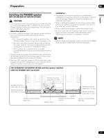
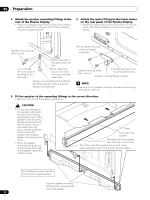
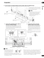
Preparation 05 English 4. Fix the speaker mounting fittings and the speaker with the supplied screws. Attach the speaker in the center first, and then both sides with the supplied screws. The screw hole at the bottom of the speaker mounting fitting is used when the Plasma Display is installed on the wall. It is not used when installed with the stand. NOTE Speaker mounting screw (M5 x 10 mm) Screw hole • If after attaching the speaker its position needs to be adjusted horizontally or vertically, first loosen the speaker mounting screws, reposition and then tighten the screws again at the appropriate position. Speaker mounting screw (M5 x 10 mm) Screw hole Speaker mounting screw (M5 x 10 mm) Screw hole 5. Connect the supplied speaker cables to the back of Plasma Display. Connect the cables correctly with respect to the polarity of the Plasma Display and the speaker terminals, that is, cable to terminals and cable to terminals. To do so, connect the cable with the gray line to the terminals and the white cable to the terminals. Gray line White Gray line Black (-) 6. Connect the other end of the speaker cables to the speaker. Connect the cables correctly with respect to the polarity of the Plasma Display and the speaker terminals, that is, cable to terminals and cable to terminals. To do so, connect the cable with the gray line to the terminals and the white cable to the terminals. Red • Press the lever and insert the end of the cable. (+) • When you release the lever, it clamps onto the speaker cable. White Gray Red Black Red line Lever Speaker terminal Speaker terminal Speaker cable Speaker terminal NOTE • If you insert the speaker cable • If there is a short in the + and - cables caused by an exposed too far so that the insulation is lead wire, excessive load may be applied to the Plasma touching the speaker terminal, Display, resulting in interrupted operation or malfunction. you may not get any sound. • Incorrect connections of the speaker cable to the right or left • Check if the end of the speaker cables are securely connected to the terminals by slightly tugging on the cable after making connections. Loose connections may result in of the Plasma Display terminals with respect to the polarity may result in insufficient stereo sound effects, delivering poor bass sounds or unstable sound image. sound dropouts or noise. 23 En
-
 1
1 -
2
-
3
-
4
-
5
-
6
-
7
-
8
-
9
-
10
-
11
-
12
-
13
-
14
-
15
-
16
-
17
-
 18
18 -
 19
19 -
 20
20 -
 21
21 -
 22
22 -
 23
23 -
 24
24 -
 25
25 -
 26
26 -
 27
27 -
 28
28 -
29
-
30
-
31
-
32
-
33
-
34
-
35
-
36
-
37
-
38
-
39
-
40
-
41
-
42
-
43
-
44
-
45
-
46
-
47
-
48
-
49
-
50
-
51
-
52
-
53
-
54
-
55
-
56
-
57
-
58
-
59
-
60
-
61
-
62
-
63
-
64
-
65
-
66
-
67
-
68
-
69
-
70
-
71
-
72
-
73
-
74
-
75
-
76
-
77
-
78
-
79
-
80
-
81
-
82
-
83
-
84
-
85
-
86
-
87
-
88
-
89
-
90
-
91
-
92
-
93
-
94
-
95
-
96
-
97
-
98
-
99
-
100
-
101
-
102
-
103
-
104
-
105
-
106
-
107
-
108
-
109
-
110
-
111
-
112
-
113
-
114
-
115
-
116
-
117
-
118
-
119
-
120
-
121
-
122
-
123
-
124
-
125
-
126
-
127
-
128
-
129
-
130
-
131
-
132
-
133
-
134
-
135
-
136
-
137
-
138
-
139
-
140
-
141
-
142
-
143
-
144
-
145
-
146
-
147
-
148
-
149
-
150
-
151
-
152
-
153
-
154
-
155
-
156
-
157
-
158
-
159
-
160
-
161
-
162
-
163
-
164
-
165
-
166
-
167
-
168
-
169
-
170
-
171
-
172
-
173
-
174
-
175
-
176
-
177
-
178
-
179
-
180
-
181
-
182
-
183
-
184
-
185
-
186
-
187
-
188
-
189
-
190
-
191
-
192
-
193
-
194
-
195
-
196
-
197
-
198
-
199
-
200
-
201
-
202
-
203
-
204
-
205
-
206
-
207
-
208
-
209
-
210
-
211
-
212
-
213
-
214
-
215
-
216
-
217
-
218
-
219
-
220
-
221
-
222
-
223
-
224
-
225
-
226
-
227
-
228
-
229
-
230
-
231
-
232
-
233
-
234
-
235
-
236
-
237
-
238
-
239
-
240
-
241
-
242
-
243
-
244
-
245
-
246
-
247
-
248
-
249
-
250
-
251
-
252
-
253
-
254
-
255
-
256
-
257
-
258
-
259
-
260
-
261
-
262
-
263
-
264
-
265
-
266
-
267
-
268
-
269
-
270
-
271
-
272
-
273
-
274
-
275
-
276
-
277
-
278
-
279
-
280
-
281
-
282
-
283
-
284
-
285
-
286
-
287
-
288
-
289
-
290
-
291
-
292
 |
 |
