Ricoh Aficio SP 4310N Manuals - Page 19
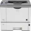
Exterior: Rear View, the printer.
 |
View all Ricoh Aficio SP 4310N manuals
Add to My Manuals
Save this manual to your list of manuals |
Page 19 highlights
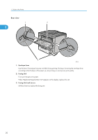
Exterior: Rear View Exterior: Rear View 1 CEE003 1. Controller Board Slide this out to install options such as the SDRAM module or printer hard disk. Plug cables such as a USB cable and Ethernet cable into their connectors. 2. Rear Cover Remove this to replace the fusing unit. 3. Power Connector Connect the power cord to the printer here. Insert the other end of the cable into a nearby wall outlet. 4. Paper Tray Cover Keeps paper in the tray free of dust. 5. Intake Vent Prevents the printer's internal components overheating by letting in cool air through this vent. Do not block or obstruct the ventilator areas. Doing so can result in malfunctions caused by build up of heat inside the printer. 6. SD Card Slots Remove the cover and install SD cards here. 7. Optional Interface Board Slot Insert an optional Wireless LAN interface unit, Gigabit Ethernet board, or 1284 interface board in this slot. 8. Ethernet Port Use a network interface cable to connect the printer to the network. 9. USB Port B Use a USB cable to connect the printer to a computer. 17
-
 1
1 -
2
-
3
-
4
-
5
-
6
-
7
-
8
-
9
-
10
-
11
-
12
-
13
-
 14
14 -
 15
15 -
 16
16 -
 17
17 -
 18
18 -
 19
19 -
 20
20 -
 21
21 -
 22
22 -
 23
23 -
 24
24 -
25
-
26
-
27
-
28
-
29
-
30
-
31
-
32
-
33
-
34
-
35
-
36
-
37
-
38
-
39
-
40
-
41
-
42
-
43
-
44
-
45
-
46
-
47
-
48
-
49
-
50
-
51
-
52
-
53
-
54
-
55
-
56
-
57
-
58
-
59
-
60
-
61
-
62
-
63
-
64
-
65
-
66
-
67
-
68
-
69
-
70
-
71
-
72
-
73
-
74
-
75
-
76
-
77
-
78
-
79
-
80
-
81
-
82
-
83
-
84
-
85
-
86
-
87
-
88
-
89
-
90
-
91
-
92
-
93
-
94
-
95
-
96
-
97
-
98
-
99
-
100
-
101
-
102
-
103
-
104
-
105
-
106
-
107
-
108
-
109
-
110
-
111
-
112
-
113
-
114
-
115
-
116
-
117
-
118
-
119
-
120
-
121
-
122
-
123
-
124
-
125
-
126
-
127
-
128
-
129
-
130
-
131
-
132
-
133
-
134
-
135
-
136
-
137
-
138
-
139
-
140
-
141
-
142
-
143
-
144
-
145
-
146
-
147
-
148
-
149
-
150
-
151
-
152
-
153
-
154
-
155
-
156
-
157
-
158
-
159
-
160
-
161
-
162
-
163
-
164
-
165
-
166
-
167
-
168
-
169
-
170
-
171
-
172
-
173
-
174
-
175
-
176
-
177
-
178
-
179
-
180
-
181
-
182
-
183
-
184
-
185
-
186
-
187
-
188
-
189
-
190
-
191
-
192
-
193
-
194
-
195
-
196
-
197
-
198
-
199
-
200
-
201
-
202
-
203
-
204
-
205
-
206
-
207
-
208
-
209
-
210
-
211
-
212
-
213
-
214
-
215
-
216
-
217
-
218
-
219
-
220
-
221
-
222
-
223
-
224
-
225
-
226
-
227
-
228
-
229
-
230
-
231
-
232
-
233
-
234
-
235
-
236
-
237
-
238
-
239
-
240
-
241
-
242
-
243
-
244
-
245
-
246
-
247
-
248
-
249
-
250
-
251
-
252
 |
 |
