Ricoh C410DN Hardware Guide - Page 15
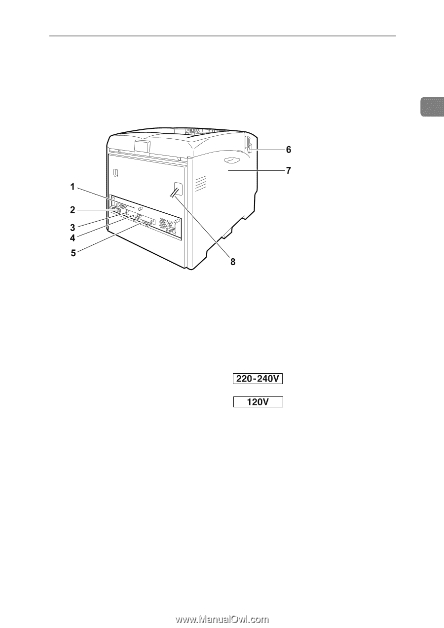
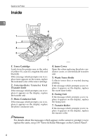
Exterior: Rear View, Controller Board, Ethernet Port, USB Port, Optional Interface Board Slots - toner cartridges
 |
UPC - 026649025341
View all Ricoh C410DN manuals
Add to My Manuals
Save this manual to your list of manuals |
Page 15 highlights
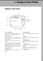
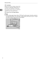
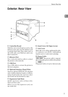
Exterior: Rear View Exterior: Rear View 1 1. Controller Board Slide this out to install options such as the memory unit, user account enhance unit or printer hard disk. Plug cables such as the USB cable and Ethernet cable into their connectors. 2. Ethernet Port Use a network interface cable to connect the printer to the network. 3. USB Port Use a USB cable to connect the printer to the host computer. 4. Optional Interface Board Slots Insert an optional IEEE 802.11b interface unit, wireless interface board, or 1284 interface board in this slot. Up to two interface board can be inserted at a time. 5. Expansion Card Slots Install expansion cards in these slots. There are three slots. When you use the expansion card, use the center slot. AQC200S 6. Front Cover (A) Open Levers 7. Left Cover Open this cover when replacing the photo conductor unit (PCU), intermediate transfer unit or waste toner cartridge. 8. Power Cable The power cable is separated. Connect the power cable to the printer. The power cable is fixed to the back side. 3
-
 1
1 -
2
-
3
-
4
-
5
-
6
-
7
-
8
-
9
-
 10
10 -
 11
11 -
 12
12 -
 13
13 -
 14
14 -
 15
15 -
 16
16 -
 17
17 -
 18
18 -
 19
19 -
 20
20 -
21
-
22
-
23
-
24
-
25
-
26
-
27
-
28
-
29
-
30
-
31
-
32
-
33
-
34
-
35
-
36
-
37
-
38
-
39
-
40
-
41
-
42
-
43
-
44
-
45
-
46
-
47
-
48
-
49
-
50
-
51
-
52
-
53
-
54
-
55
-
56
-
57
-
58
-
59
-
60
-
61
-
62
-
63
-
64
-
65
-
66
-
67
-
68
-
69
-
70
-
71
-
72
-
73
-
74
-
75
-
76
-
77
-
78
-
79
-
80
-
81
-
82
-
83
-
84
-
85
-
86
-
87
-
88
-
89
-
90
-
91
-
92
-
93
-
94
-
95
-
96
-
97
-
98
-
99
-
100
-
101
-
102
-
103
-
104
-
105
-
106
-
107
-
108
-
109
-
110
-
111
-
112
-
113
-
114
-
115
-
116
-
117
-
118
-
119
-
120
-
121
-
122
-
123
-
124
-
125
-
126
-
127
-
128
-
129
-
130
-
131
-
132
-
133
-
134
-
135
-
136
-
137
-
138
-
139
-
140
-
141
-
142
-
143
-
144
-
145
-
146
-
147
-
148
-
149
-
150
-
151
-
152
-
153
-
154
-
155
-
156
-
157
-
158
-
159
-
160
-
161
-
162
-
163
-
164
-
165
-
166
-
167
-
168
-
169
-
170
-
171
-
172
-
173
-
174
-
175
-
176
-
177
-
178
-
179
-
180
-
181
-
182
-
183
-
184
-
185
-
186
-
187
-
188
-
189
-
190
-
191
-
192
-
193
-
194
-
195
-
196
-
197
-
198
-
199
-
200
-
201
-
202
-
203
-
204
 |
 |