Ricoh IM 430F User Guide - Page 54
Connecting to the Extra Ethernet Interface with the USB Device Server Option
 |
View all Ricoh IM 430F manuals
Add to My Manuals
Save this manual to your list of manuals |
Page 54 highlights
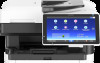
1. Getting Started Check that the interface board is firmly connected to the controller board. 5. Tighten the two screws to secure the interface board. 6. Connect the USB device server to the machine. For details, see the Setup Guide provided with the USB device server. Connecting to the Extra Ethernet Interface with the USB Device Server Option This section describes how to connect an Ethernet interface cable to the Ethernet port of the optional USB Device Server. USB Device Server Option is an interface board for adding an extra Ethernet port. If you install USB Device Server Option, you can connect two Ethernet cables simultaneously: one to the machine's Ethernet port and one to the Ethernet port of USB Device Server Option. An IP address can be assigned to each connection, and you can use one machine to print from different network segments. Remove the cover of USB2.0 port on the machine and connect the port to the USB port of the USB device server. • A network interface cable with a ferrite core must be used for RF interference suppression. • Use the following Ethernet cables. • When using 100BASE-TX/10BASE-T: Unshielded Twisted Pair Cable (UTP) or Shielded Twisted Pair Cable (STP) and Category type 5 or more • When using 1000BASE-T: Unshielded Twisted Pair Cable (UTP) or Shielded Twisted Pair Cable (STP) and Category type 5e or more 1. Make sure the main power switch is turned off. 52
-
 1
1 -
2
-
3
-
4
-
5
-
6
-
7
-
8
-
9
-
10
-
11
-
12
-
13
-
14
-
15
-
16
-
17
-
18
-
19
-
20
-
21
-
22
-
23
-
24
-
25
-
26
-
27
-
28
-
29
-
30
-
31
-
32
-
33
-
34
-
35
-
36
-
37
-
38
-
39
-
40
-
41
-
42
-
43
-
44
-
45
-
46
-
47
-
48
-
 49
49 -
 50
50 -
 51
51 -
 52
52 -
 53
53 -
 54
54 -
 55
55 -
 56
56 -
 57
57 -
 58
58 -
 59
59 -
60
-
61
-
62
-
63
-
64
-
65
-
66
-
67
-
68
-
69
-
70
-
71
-
72
-
73
-
74
-
75
-
76
-
77
-
78
-
79
-
80
-
81
-
82
-
83
-
84
-
85
-
86
-
87
-
88
-
89
-
90
-
91
-
92
-
93
-
94
-
95
-
96
-
97
-
98
-
99
-
100
-
101
-
102
-
103
-
104
-
105
-
106
-
107
-
108
-
109
-
110
-
111
-
112
-
113
-
114
-
115
-
116
-
117
-
118
-
119
-
120
-
121
-
122
-
123
-
124
-
125
-
126
-
127
-
128
-
129
-
130
-
131
-
132
-
133
-
134
-
135
-
136
-
137
-
138
-
139
-
140
-
141
-
142
-
143
-
144
-
145
-
146
-
147
-
148
-
149
-
150
-
151
-
152
-
153
-
154
-
155
-
156
-
157
-
158
-
159
-
160
-
161
-
162
-
163
-
164
-
165
-
166
-
167
-
168
-
169
-
170
-
171
-
172
-
173
-
174
-
175
-
176
-
177
-
178
-
179
-
180
-
181
-
182
-
183
-
184
-
185
-
186
-
187
-
188
-
189
-
190
-
191
-
192
-
193
-
194
-
195
-
196
-
197
-
198
-
199
-
200
-
201
-
202
-
203
-
204
-
205
-
206
-
207
-
208
-
209
-
210
-
211
-
212
-
213
-
214
-
215
-
216
-
217
-
218
-
219
-
220
-
221
-
222
-
223
-
224
-
225
-
226
-
227
-
228
-
229
-
230
-
231
-
232
-
233
-
234
-
235
-
236
-
237
-
238
-
239
-
240
-
241
-
242
-
243
-
244
-
245
-
246
-
247
-
248
-
249
-
250
-
251
-
252
-
253
-
254
-
255
-
256
-
257
-
258
-
259
-
260
-
261
-
262
-
263
-
264
-
265
-
266
-
267
-
268
-
269
-
270
-
271
-
272
-
273
-
274
-
275
-
276
-
277
-
278
-
279
-
280
-
281
-
282
-
283
-
284
-
285
-
286
-
287
-
288
-
289
-
290
-
291
-
292
-
293
-
294
-
295
-
296
-
297
-
298
-
299
-
300
-
301
-
302
-
303
-
304
-
305
-
306
-
307
-
308
-
309
-
310
-
311
-
312
 |
 |
