Ridgid R4512 Owners Manual
Ridgid R4512 Manual
 |
View all Ridgid R4512 manuals
Add to My Manuals
Save this manual to your list of manuals |
Ridgid R4512 manual content summary:
- Ridgid R4512 | Owners Manual - Page 1
OPERATOR'S MANUAL 10 in. TABLE SAW R4512 45 Your table saw has been engineered and manufactured to our high standards for dependability, ease of operation, and operator safety. When properly cared for, it will give you years of rugged, trouble-free performance. WARNING: To reduce the risk of - Ridgid R4512 | Owners Manual - Page 2
Specific Safety Rules...4-5 Symbols...6-7 Electrical...8-9 Glossary of Terms...10 Features...11-13 Tools Needed ...14 Loose Parts...15-16 Assembly...17-28 Operation...29-44 Adjustments...45-48 Maintenance...49-50 Troubleshooting...51-52 Warranty...53 Parts Ordering/Service - Ridgid R4512 | Owners Manual - Page 3
. Failure to follow all instructions listed below, may result in electric shock, fire and/or serious personal injury. READ ALL INSTRUCTIONS KNOW YOUR POWER TOOL. Read the operator's manual carefully. Learn the saw's applications and limitations as well as the specific potential hazards related to - Ridgid R4512 | Owners Manual - Page 4
. When servicing use only identical replacement parts. Use of any other parts may create a hazard or cause product damage. Use only recommended accessories listed in this manual or addendums. Use of accessories that are not listed may cause the risk of personal injury. Instructions for safe use - Ridgid R4512 | Owners Manual - Page 5
the saw blade using a push stick. e) Not ripping work that is twisted or warped or does not have a straight edge to guide along the fence. IF THE POWER SUPPLY CORD IS DAMAGED, it must be replaced only by the manufacturer or by an authorized service center to avoid risk. AVOID AWKWARD OPERATIONS - Ridgid R4512 | Owners Manual - Page 6
injury hazard. To reduce the risk of injury, user must read and understand operator's manual before using this product. Always wear eye protection marked to comply with ANSI Z87.1. Failure to keep your hands away from the blade will result in serious personal injury. V A Hz W min no .../min Wet - Ridgid R4512 | Owners Manual - Page 7
. When servicing, use only identical replacement parts. WARNING: To avoid serious personal injury, do not attempt to use this product until you read thoroughly and understand completely the operator's manual. If you do not understand the warnings and instructions in the operator's manual, do - Ridgid R4512 | Owners Manual - Page 8
motor's horsepower rating. A line intended only for lights cannot properly carry a power tool motor. Wire that is heavy enough for a short distance will be too light for a greater distance. A line that can support one power tool may not be able to support two or three tools. Grounding Instructions - Ridgid R4512 | Owners Manual - Page 9
plug and replace it with a 3-prong 240 volt, 15 amp. UL listed plug. Connect the power cord white and black leads, respectively, to the "hot" plug blade terminals. Connect the power cord green grounding wire to the plug ground prong terminal. Reinstall the rear panel. Plug your table saw into - Ridgid R4512 | Owners Manual - Page 10
in one minute. Ripping or Rip Cut A cutting operation along the length of the workpiece. Riving Knife/Spreader/Splitter (table saws) A metal piece, slightly thinner than the kerf, which helps keep the kerf open and also helps to prevent kickback. Saw Blade Path The area over, under, behind, or in - Ridgid R4512 | Owners Manual - Page 11
MITER GAUGE GROOVE spreader/ RIVING KNIFE ANTI-KICKBACK PAWLS BLADE GUARD No Load Speed 3,450 r/min. (RPM) Cutting Depth at 0 3-1/4 in. Cutting Depth at 45 2-1/4 in. RIP FENCE MITER GAUGE GROOVE RIP FENCE SCALE TABLE EXTENSION MITER gauge RIP FENCE STORAGE BRACKETS FRONT bevel RAIL - Ridgid R4512 | Owners Manual - Page 12
of the rip fence for use with optional clamps and accessories. RIP SCALE - Located on the front rail, the easy-to-read rip scale provides precise measurements for rip cuts. SPREADER / RIVING KNIFE - A removable metal piece of the blade guard assembly, slightly thinner than the saw blade, which helps - Ridgid R4512 | Owners Manual - Page 13
The upper portion of the blade projects up through the table and is surrounded by an insert called the throat plate. The height of the blade is set with a handwheel on the front of the cabinet. Detailed instructions are provided in the Operation section of this manual for the basic cuts: cross - Ridgid R4512 | Owners Manual - Page 14
tools needed The following tools (not included or drawn to scale) are needed for assembly and alignment: Framing Square Phillips Screwdriver COMBINATION SQUARE Flat Blade Screwdriver WRENCH 4 mm, 8 mm, 10 mm, 13 mm, 14 mm C-CLAMP SOCKET WRENCH (8 mm, 13 mm socket) Fig. 7 14 - Ridgid R4512 | Owners Manual - Page 15
and Knob........ 1 G. Push Stick 1 H. Blade Wrench, open end 1 I. Blade Wrench, closed end 1 J. Hex Keys (3 mm, 4 mm, 5 mm, 6 mm, 8 mm 1 K. Rear Rail 2 L. Front Rail 2 M. Rail Connector Bar 3 N. Table Extensions 2 O. Spreader Bar 1 P. Dust Chute 1 Q. Throat Plate 1 R. Front End Cap (left - Ridgid R4512 | Owners Manual - Page 16
LOOSE PARTS C A H F E B D G A. Leg Stand Side Sections 2 B. Leg Stand Front and Back 2 C. Outer Corners 4 D. Caster Assembly 4 E. Center Support 1 I Fig. 9 F. Rear Axle 1 G. Front Axle 1 H. Rip Fence Storage Brackets 2 I. Foot 4 16 - Ridgid R4512 | Owners Manual - Page 17
operated the tool. NOTE: Remove the foam block from between the saw's housing and the motor. The saw is factory set for accurate cutting. After assembling it, check for accuracy. If shipping has influenced the settings, refer to specific procedures explained in this manual. If any parts - Ridgid R4512 | Owners Manual - Page 18
INSTALLING THE TABLE EXTENSIONS See Figures 10 - 11. NOTE: It is helpful to place two inch-thick boards on the floor before lifting the saw table and motor housing from the box. This will make it easier to assemble parts, and to move the saw and set it upright. Lift the saw table and motor housing - Ridgid R4512 | Owners Manual - Page 19
ASSEMBLY ASSEMBLING THE LEG stand onto the saw CABINET See Figures 13 - 14. WARNING: Only install the dust chute when using a four inch dust collection system. Failure to heed this warning could result in serious personal injury or death. Clean saw dust center support to the front axle assembly. - Ridgid R4512 | Owners Manual - Page 20
the leg stand, aligning the holes in the caster assembly with the holes in the leg stand. NOTE: Position the pedal as shown, so that it will be in the front of the saw when the saw is upright. Locate the following from the small fastener pack: 8 Bolts (M8 x 16) Insert the bolts into the - Ridgid R4512 | Owners Manual - Page 21
. Slide the washer over the bolt. Screw the knob securely onto the bolt. ACCESSORY STORAGE See Figure 22. Storage for the blade, blade wrench and miter gauge is located on the side of the saw. The miter gauge may be stored by sliding it into the slots. The push stick contains a magnet. When not - Ridgid R4512 | Owners Manual - Page 22
. Make sure the blade nut is securely tightened. Do not overtighten. Rotate the blade by hand to make sure it turns freely. Lower the saw blade and install the throat plate. throat plate blade arbor OPEN END blade WRENCH blade blade washer blade nut Fig. 23 closed end blade WRENCH Fig. 24 - Ridgid R4512 | Owners Manual - Page 23
. To install the throat plate, slip the tab underneath the saw table at the back of the saw and push down to secure in place. To remove the throat plate, place your index finger in the hole and lift the front end, pulling the throat plate out toward the front of the saw. ASSEMBLING THE RAILS See - Ridgid R4512 | Owners Manual - Page 24
front rail: Slide eight hex head bolts into the groove on the back of the assembled front rail. Align the bolts with and insert the bolts into the holes on the front of the saw table and table extensions. Using a 13 mm wrench, tighten the four center nuts. Do not tighten completely. Tighten - Ridgid R4512 | Owners Manual - Page 25
rail. Check the table and extensions to make sure all assembled parts are flush and level. If the table extensions, rip fence, and rails are not with the tabs facing away from the saw table. Slide a hex head bolt into the groove on the front rail and insert the bolt through the tab in the - Ridgid R4512 | Owners Manual - Page 26
NOTE: The spreader/riving knife must be placed in the through cutting, or "up" position (spreader position), for all other cutting operations. Unplug the saw. To place in spreader position (or "up" position for all through cutting): Remove the throat plate. Raise the saw blade by turning the - Ridgid R4512 | Owners Manual - Page 27
it is parallel to the table. Lock the guard in place by pushing the guard lever down. NOTE: Blade alignment with the spreader can be adjusted for different blade widths. Refer to: To Check and Align the Spreader/Riving Knife and Saw Blade. Check the blade guard assembly for clearances and free - Ridgid R4512 | Owners Manual - Page 28
TO Check and Align the spreader/ riving knife and Saw Blade See Figure 40. To check alignment of the spreader/riving knife: Unplug the saw. Raise the saw blade by turning the height/bevel adjusting handwheel clockwise. Remove the anti-kickback pawls and blade guard assembly. Place a framing - Ridgid R4512 | Owners Manual - Page 29
not operate the saw without the blade guard unless specifically instructed to do so. APPLICATIONS You may use this tool for the purposes listed below: Straight line cutting operations such as cross cutting, ripping, mitering, beveling, and compound cutting Dado cuts with optional accessories - Ridgid R4512 | Owners Manual - Page 30
the underside. Be sure the screw is recessed. Use it on non-through cuts. AUXILIARY FENCE An auxiliary fence is a device used to close the gap between the rip fence and the saw table. Always make and use an auxiliary fence when ripping material 1/8 in. or thinner. How to Make and ATTACH an auxiliary - Ridgid R4512 | Owners Manual - Page 31
OPERATION FEATHERBOARD A featherboard is a device used to help control the workpiece by guiding it securely against the table or fence. the table with a C-clamp. Test that it can resist kickback. HOW TO MOUNT A FEATHERBOARD See Figure 45. Completely lower the saw blade. Position the rip fence to - Ridgid R4512 | Owners Manual - Page 32
Dado and rabbet cuts are non-through cuts which can be either rip cuts or cross cuts. Carefully read and understand all sections of this operator's manual before attempting any operation. WARNING: Do not use blades the cut. Always provide proper support for the wood as it comes out of the saw. 32 - Ridgid R4512 | Owners Manual - Page 33
as it will go, the blade should be at 90° to the saw table and the bevel indicator should point to 0°. Note: When the saw blade is 90° to the saw table, the saw blade should be square with the saw table. (See the Adjustments section of this manual to square the saw blade.) GULLET Fig. 47 to lower - Ridgid R4512 | Owners Manual - Page 34
saw table, push the fence towards the front rail to align the fence to the saw table. Push the locking handle down to secure the fence. Check for a smooth gliding action. If adjustments are needed, see To Check the Alignment of the Rip Fence to the Blade in the Adjustments section of this manual - Ridgid R4512 | Owners Manual - Page 35
with the blade at a zero angle (straight up). Unplug the saw. Loosen the rip fence by lifting the locking handle. Set the rip fence gently against the blade tip edge. Loosen the screw on the scale indicator and align with the 0 mark as shown. Tighten the screw and check the dimension and - Ridgid R4512 | Owners Manual - Page 36
. If the distances are the same, the blade is square. If the distances are different: Place spreader/riving knife in "down" position then lower the blade. Loosen the four adjusting bolts. NOTE: The adjusting bolts are located under the saw table. If the back of the blade was too far from the - Ridgid R4512 | Owners Manual - Page 37
proper procedures and necessary accessories. Your local library has many books on table saw usage and specialized woodworking procedures for your reference. The blade provided with the saw is a high-quality combination blade suitable for ripping and cross cut operations. Carefully check all setups - Ridgid R4512 | Owners Manual - Page 38
to the correct depth for the workpiece. Position the rip fence the desired distance from the blade for the cut and securely lock the handle. When ripping a long workpiece, place a support the same height as the table surface behind the saw for the cut work. Make sure the wood is clear of the - Ridgid R4512 | Owners Manual - Page 39
OPERATION making a bevel cross cut See Figures 61 - 62. WARNING: Make sure the blade guard assembly is installed and working properly to avoid possible serious injury. VIEWED FROM THE SIDE, BELOW THE TABLE SAW TO unlock WARNING: The miter gauge must be on the right side of the blade to avoid - Ridgid R4512 | Owners Manual - Page 40
is clear of the blade before turning on the saw. When ripping a long workpiece, place a support the same height as the table surface behind the saw for the cut work. Turn the saw on. Position the workpiece flat on the table with the edge flush against the rip fence. Let the blade build up to - Ridgid R4512 | Owners Manual - Page 41
the blade guard assembly is installed and working properly to avoid possible serious injury. WARNING: Never make freehand cuts (cuts without the miter gauge or rip fence), which can result in serious injury. LARGE PANEL CUT RIP FENCE Fig. 64 SUPPORTS Fig. 65 Place a support the same height as - Ridgid R4512 | Owners Manual - Page 42
non-through cut such as rabbets or dadoes. To avoid personal injury, always use push blocks, push sticks, and featherboards. Unplug the saw. Remove the blade guard and anti-kickback pawls. Place spreader / riving knife in "down" position. Loosen the height lock knob. Adjust the bevel angle - Ridgid R4512 | Owners Manual - Page 43
spreader/riving knife. Remove the blade nut, outer blade washer, saw blade, inner blade washer, and spacer. NOTE: Always store the blade washer and throat plate in a secure location. Reinstall the inner blade washer. Mount the dado blade, according to manufacturer instructions, using the blade - Ridgid R4512 | Owners Manual - Page 44
OPERATION CONSTRUCTING a TABLE EXTENSION See Figure 68. You may construct a wood table extension to support larger workpieces. The finished height of the table extension should be 1-3/4 in. The finished length and width should be 27 in. x 14-5/8 in. Assemble the pieces as shown. The finished - Ridgid R4512 | Owners Manual - Page 45
replace the blade with an accessory blade, follow the instructions provided with the accessory. OPEN END blade WRENCH CLOSED END blade WRENCH Fig. 70 spacer Blade inner Blade washer OUTER Blade washer Blade nut BLADE release lever arbor shaft Fig. 71 THROAT PLATE spreader/ RIVING KNIFE Fig - Ridgid R4512 | Owners Manual - Page 46
during assembly. After extensive use, it may need to be checked. Unplug the saw. Raise the blade. Remove the blade guard. If the blade is square contacts the flat part of the saw blade, not the blade teeth. Turn the bevel handle until the bevel indicator points to zero. If the bevel handle - Ridgid R4512 | Owners Manual - Page 47
using a 45° triangle and the steps above. TO CHECK THE ALIGNMENT OF THE RIP FENCE TO THE BLADE See Figure 76. WARNING: To reduce the risk of injury, always make sure the rip fence is parallel to the blade before beginning any operation. Unplug the saw. Raise the locking handle to permit the rip - Ridgid R4512 | Owners Manual - Page 48
guard assembly when the adjustment is complete. Unplug the saw. Place the rip fence on the saw table so that it lightly touches the right side of the saw blade. Lock the rip fence in place. Loosen pan head screw and adjust the right indicator so that the red line is located over the "zero - Ridgid R4512 | Owners Manual - Page 49
. Make sure the throat plate is in good condition and in position. Check the blade guard assembly. To maintain the table surfaces, fence, and rails, periodically apply paste wax to them and buff to provide smooth functioning. To prevent work from slipping during cutting operation, Do not wax - Ridgid R4512 | Owners Manual - Page 50
key, remove the screws that secure the back panel. Inspect the dust chute and attached dust collection devices to clear away sawdust or other debris. Replace the back panel. TO REMOVE AND CHANGE belt See Figure 79. Lower the saw blade. Using a 4 mm hex key, remove the screws that secure the - Ridgid R4512 | Owners Manual - Page 51
groove" in the Operation section. Slow the feed rate. Align the rip fence. See "To check and align the spreader/riving knife and saw blade" in the Assembly section. Replace the wood. Always cut with convex side to table surface. Wood edges away from rip fence when ripping. Rip fence is misaligned - Ridgid R4512 | Owners Manual - Page 52
TROUBLESHOOTING Problem Saw does not make accurate 90˚ or 45˚ cuts. Height/bevel adjusting handwheel is hard to turn. Saw does not start. Blade makes poor cuts. Blade does not lower when turning height/bevel adjusting handwheel. Motor labors in rip cut. Cause Solution Positive stops inside - Ridgid R4512 | Owners Manual - Page 53
defect resulting from misuse, abuse, neglect, alteration, modification or repair by other than an authorized service center for RIDGID® branded hand held and stationary power tools. Consumable accessories provided with the tool such as, but not limited to, blades, bits and sand paper are not covered - Ridgid R4512 | Owners Manual - Page 54
OPERATOR'S MANUAL 10 in. TABLE SAW R4512 Customer Service Information For parts or service, contact your nearest RIDGID authorized service center. Be sure to provide all relevant information when you call or visit. For the location of the authorized service center nearest you, please call 1-866-539 - Ridgid R4512 | Owners Manual - Page 55
MANUAL DEL OPERADOR SIERRA DE MESA DE 254 mm (10 pulg.) R4512 45 Su sierra de mesa ha sido diseñada y riesgo de lesiones, el usuario debe leer y comprender el manual del operador antes de usar este producto. Le agradecemos la compra de un producto RIDGID®. GUARDE ESTE MANUAL PARA FUTURAS CONSULTAS - Ridgid R4512 | Owners Manual - Page 56
Introducción...2 Reglas de seguridad generales...3-4 Reglas de seguridad específicas...4-5 Símbolos...6-7 Aspectos eléctricos...8-9 Glosario de términos...10 Características...11-13 Herramientas necesarias ...14 Piezas sueltas...15-16 Armado...17-28 Funcionamiento...29-44 - Ridgid R4512 | Owners Manual - Page 57
ÉCTRICA. Proporcione mantenimiento con cuidado a Lea cuidadosamente el manual del operador. Aprenda los las herramientas. Manténgalas afiladas de exteriores y reducen el riesgo de descargas eléctricas. usted hacia partes en movimiento. Se recomiendan guantes SIEMPRE MANTENGA EL PROTECTOR DE - Ridgid R4512 | Owners Manual - Page 58
UNA ATMÓSFERA EXPLOSIVA. El chispeo normal del motor podría encender los gases presentes. REVISE PERIÓDICAMENTE de un diámetro máximo de 254 mm (10 pulg.). Antes de efectuar un corte verifique que se detiene rápidamente y la pieza de trabajo sale proyectada hacia el operador. Puede tirar de la - Ridgid R4512 | Owners Manual - Page 59
corte a inglete y oriente la pieza de trabajo. NUNCA se pare ni tenga ninguna parte del cuerpo en línea con la trayectoria de la hoja de la sierra. NUNCA se los accesorios señalados en este manual o en los apéndices. El uso de accesorios no mencionados en este manual plantea el riesgo de que - Ridgid R4512 | Owners Manual - Page 60
del operador Protección ocular Indica un peligro posible de lesiones personales. Para reducir el riesgo de lesiones, el usuario debe leer y comprender el manual del operador antes de usar este producto. Siempre póngase protección ocular con la marca de cumplimiento de la norma ANSI Z87.1. V A Hz - Ridgid R4512 | Owners Manual - Page 61
del operador. Si no comprende los avisos de advertencia y las instrucciones del manual del operador, no utilice este producto. Llame al departamento de atención al consumidor de RIDGID® y le brindaremos asistencia. ADVERTENCIA: Cualquier herramienta eléctrica en funcionamiento puede lanzar objetos - Ridgid R4512 | Owners Manual - Page 62
pérdida de potencia y un recalentamiento del motor. Básese en la tabla suministrada abajo 16 16 16 14 14 12 100' 16 16 14 12 10 - **Se usa en los circuitos de calibre 12, 20 amp con un cordón dañado, ya que si toca la parte dañada puede producirse una descarga eléctrica, y las consecuentes - Ridgid R4512 | Owners Manual - Page 63
que aseguran el panel trasero de la sierra. Retire el panel. Baje el motor hasta su punto mínimo. La caja de conexiones está ubicada en la parte superior del motor. Retire el tornillo Phillips ubicado en la parte posterior de la caja de conexiones y después levante la cubierta. Retire de los - Ridgid R4512 | Owners Manual - Page 64
y da mantenimiento correctamente, sirve para detener la pieza de trabajo para no ser lanzada hacia atrás, hacia la parte frontal la sierra durante una operación de corte al hilo. Árbol Es el eje donde se monta una hoja mientras se le efectúa una operación de corte, taladrado, cepillado o lijado. 10 - Ridgid R4512 | Owners Manual - Page 65
CARACTERÍSTICAS ESPECIFICACIONES DEL PRODUCTO Árbol de la hoja de corte 16 mm (5/8 pulg.) Diámetro de la hoja 254 mm (10 pulg.) Inclinación de la hoja 0˚ - 45˚ Especificaciones eléctricas 120 V~, 13 A, 60 Hz, separador / cuchilla separadora PROTECCIÓN DE LA HOJA HOJA trinquetes - Ridgid R4512 | Owners Manual - Page 66
ón impresa en la herramienta y en el manual del operador así como ciertos conocimientos sobre el sierra viene con una hoja de corte de 254 mm (10 pulg.) y 36 dientes con puntas de carburo dientes. - El volante de ajuste de altura, ubicado en la parte frontal del gabinete, se usa para bajar y subir la - Ridgid R4512 | Owners Manual - Page 67
altura de la hoja se fija por medio de un volante ubicado en la parte frontal de la caja. Para recibir paneles anchos, la sierra de mesa dispone detalladas para los cortes básicos en la sección Funcionamiento de este manual: cortes rectos transversales, cortes en inglete, cortes en bisel y cortes - Ridgid R4512 | Owners Manual - Page 68
(no incluido o dibujado para escalar) para el armado y la alineación: Escuadra de carpintero Destornillador Phillips ESCUADRA DE COMBINACIÓN Destornillador de punta plana WRENCH 4 mm, 8 mm, 10 mm, 13 mm, 14 mm prensa en C llave de casquillo (8 mm, 13 mm casquillo) Fig. 7 14 - Ridgid R4512 | Owners Manual - Page 69
PIEZAS SUELTAS Con la sierra de mesa vienen incluidos los siguientes artículos: A G B C E, F N Q D K L K O P M S L J HI R Fig. 8 A. Protección de la hoja 1 B. Trinquetes anticontragolpe 1 C. Guía de ingletes 1 D. Guía de corte al hilo 1 E. Volante de ajuste de altura, arandela, - Ridgid R4512 | Owners Manual - Page 70
PIEZAS SUELTAS C A H F E B D G A. Pedestal sección lateral 2 B. Pedestal frente y atrás 2 C. Esquinas exteriores 4 D. Conjunto del ruedas pivotantes 4 E. Soporte central 1 I Fig. 9 F. Eje trasero 1 G. Eje delantero 1 H. Soportes para guardar la guía de corte al hilo 2 I. Pie 4 16 - Ridgid R4512 | Owners Manual - Page 71
la exactitud de la misma. Si en el envío resultaron afectados los ajustes, consulte los procedimientos específicos explicados en este manual. Si hay alguna parte dañada o faltante, llame al 1-866-539-1710, donde le brindaremos asistencia. ADVERTENCIA: Si hay piezas dañadas o faltantes, no utilice - Ridgid R4512 | Owners Manual - Page 72
colocarla en posición vertical. Levante la mesa de la sierra y el alojamiento del motor de la caja y ubíquelos sobre las tablas como se muestra. Afloje la 24 pernos (M6 x 10) Coloque una esquina exterior por fuera de una sección del pedestal de patas. NOTA: La parte superior de la esquina - Ridgid R4512 | Owners Manual - Page 73
: Asegúrese de que se haya retirado el bloque de espuma antes de instalar el vertedero de polvo. Coloque el vertedero de polvo en la parte superior del armazón de la sierra. La palabra "FRONT" (delantero) y la flecha deben estar alineadas con el panel delantero de la sierra y las ondulaciones de - Ridgid R4512 | Owners Manual - Page 74
conjunto de ruedas pivotantes con los agujeros del pedestal de patas. NOTA: Coloque el pedal como se muestra, de manera que quede en la parte delantera de la sierra cuando esta se encuentre en posición vertical. Localice las siguientes piezas en el paquete de sujetadores pequeños: 8 pernos (M8 - Ridgid R4512 | Owners Manual - Page 75
hacia la derecha hasta que quede firmemente apretada. Deslice el volante en el perno por encima de la escala de ajuste de bisel en la parte delantera de la sierra. Deslice la arandela en el perno. Atornille la perilla firmemente al perno. INSTALACIÓN DEL VOLANTE DE AJUSTE DE BISEL Vea la - Ridgid R4512 | Owners Manual - Page 76
la tuerca de la hoja esté firmemente apretada. No apriete excesivamente. Introduzca el extremo abierto de una de las llaves de la hoja en las partes planas del árbol. Introduzca el extremo cerrado de la otra llave de tuercas de la hoja encima de la tuerca hexagonal. Sosteniendo firmemente ambas - Ridgid R4512 | Owners Manual - Page 77
LA GARGANTA Vea la figura 25. Para instalar la placa de la garganta, deslice la orejeta debajo de la mesa de la sierra, en la parte posterior de la sierra y empuje hacia abajo para asegurarla en su lugar. Para sacar la placa de garganta, coloque el índice dedo en el agujero - Ridgid R4512 | Owners Manual - Page 78
para el riel trasero) 16 tuercas (M8: 10 para el riel delantero y 6 para el parte frontal hasta la parte posterior de la guía de corte al hilo, a ambos lados de la hoja. 24 CONJUNTO DEL RIEL DELANTERO CONJUNTO DEL RIEL TRASERO Fig. 29 guía de corte al hilo Fig. 30 TORNILLOS rip fence ZERO - Ridgid R4512 | Owners Manual - Page 79
muestra, para asegurarse de que las extensiones de la mesa estén niveladas con la parte superior. Si las extensiones de la mesa y los rieles están planos y Apriete firmemente las tuercas hexagonales usando una llave de tuercas de 10 mm. escuadra de carpintero 45 Fig. 32 PERNO perno de cabeza - Ridgid R4512 | Owners Manual - Page 80
ARMADO INSTALACIÓN DE LAS TAPAS DE LOS EXTREMOS Vea la figura 35. Alinee las tapas de los extremos del riel delantero con el extremo del riel. Asegúrelas usando tornillos autorroscantes de cabeza troncocónica (M4) en cada agujero con un destornillador Phillips. Empuje las tapas del extremo - Ridgid R4512 | Owners Manual - Page 81
ARMADO PARA INSTALAR EL TRANQUETES ANTICONTRAGOLPE Y PROTECCIÓN DE LA HOJA Vea las figuras 37 - 39. ADVERTENCIA: Reemplace trinquetes lánguidos o dañado trinquetes anticontragolpe. Embote o dañó trinquetes no pueden parar una contragolpe que aumenta el riesgo de lesiones corporales serias. Los - Ridgid R4512 | Owners Manual - Page 82
dientes depunta de carburo y mida desde la hoja. Este paso asegurará quela escuadra de carpintero esté en escuadra contra la hoja desdeel frente hacia la parte trasera de la hoja. Se sabe que la hoja de la sierra y el separador están alineados cuando la escuadra de carpintero toca tanto la hoja - Ridgid R4512 | Owners Manual - Page 83
serias. ADVERTENCIA: Aunque en muchas de las ilustraciones de este manual aparece la protección de la hoja quitada para mayor claridad, CONTRAGOLPES Siempre utilice el ajuste correcto de profundidad de la hoja. La parte superior de los dientes de la hoja debe sobresalir de la pieza de trabajo - Ridgid R4512 | Owners Manual - Page 84
FUNCIONAMIENTO ayudas para cortar Vea la figura 41. Las estacas empujadoras son dispositivos empleados para empujar la pieza de trabajo por la hoja. Se pueden hacer a partir de madera de desperdicio, en varios tamaños y formas para utilizarse en proyectos específicos. El palo empujador debe ser más - Ridgid R4512 | Owners Manual - Page 85
tabla desde la punta a 6, 8, 10 y 12 pulg. (152, 203, 254, 305 mm). Taladre un agujero de 3/8 pulg. (9,5 mm) en las marcas de 8, 10 y 12 pulg. (203, 254, delante de la hoja. No coloque el peine de sujeción en la parte posterior de la hoja. Si se coloca inadecuadamente, puede producirse un - Ridgid R4512 | Owners Manual - Page 86
. Lea cuidadosamente y comprenda todas las secciones de este manual del operador antes de intentar cualquier operación. ADVERTENCIA: No que la hoja se sobrecaliente o se atore. Al medir la madera considere la parte eliminada por el corte. Asegúrese de que el corte se efectúe sale de la sierra. 32 - Ridgid R4512 | Owners Manual - Page 87
la sierra, debe esta a escuadra con dicha mesa. (Para colocar a escuadra la hoja de la sierra, vea el apartado en la sección Ajustes de este manual).. Garganta Fig. 47 para bajar volante de ajuste de altura para levantar Fig. 48 VOLANTE DE AJUSTE DE BISEL Fig. 49 33 - Ridgid R4512 | Owners Manual - Page 88
de la guía de corte al hilo con la hoja, en la sección Ajuste de este manual. Haga dos o tres cortes de prueba en restos de madera. Si los cortes no en el reborde posterior de la mesa, apriete el tornillo de sujeción de la parte posterior de la guía de corte al hilo girándolo hacia la derecha. - Ridgid R4512 | Owners Manual - Page 89
FUNCIONAMIENTO Para ajustar a la hoja el indicador de la escala de la guía de corte al hilo Vea la figura 52. Use el indicador de la guía de corte al hilo para posicionar la guía sobre la escala en el riel delantero. Nota: Para poder efectuar este ajuste, debe retirarse los trinquetes - Ridgid R4512 | Owners Manual - Page 90
pernos de ajuste se encuentran debajo de la mesa de la sierra. Si la parte posterior de la hoja estaba muy lejos de la ranura de la guía de la ranura de la guía de ingletes. Vuelva a apretar los tornillos. Si la parte posterior de la hoja estaba muy cerca de la ranura de la guía de ingletes, - Ridgid R4512 | Owners Manual - Page 91
FUNCIONAMIENTO FORMA DE EFECTUAR CORTES La hoja suministrada con la sierra es una hoja combinada de alta calidad adecuada para operaciones de corte al hilo y transversal. Verifique cuidadosamente todos los ajustes y gire la hoja una vuelta completa para asegurarse de que haya espacio libre adecuado - Ridgid R4512 | Owners Manual - Page 92
FUNCIONAMIENTO cómo efectuar cortes al hilo Vea la figura 59. CORTE AL HILO GUÍA DE CORTE AL HILO ADVERTENCIA: Asegúrese de que esté instalado y funcione adecuadamente el conjunto de protección de la hoja para evitar posibles lesiones graves. HOJA Ajuste la hoja a la profundidad correcta para - Ridgid R4512 | Owners Manual - Page 93
FUNCIONAMIENTO cómo efectuar cortes transversales en bisel Vea las figuras 61 y 62. ADVERTENCIA: Asegúrese de que esté instalado y funcione adecuadamente el conjunto de protección de la hoja para evitar posibles lesiones graves. Desmonte la guía de corte al hilo. Afloje la perilla de fijación de - Ridgid R4512 | Owners Manual - Page 94
FUNCIONAMIENTO cómo efectuar cortes al hilo en bisel Vea la figura 63. ADVERTENCIA: Asegúrese de que esté instalado y funcione adecuadamente el conjunto de protección de la hoja para evitar lesiones graves. corte al hilo en bisel GUÍA DE CORTE AL HILO HOJA EN ÁNGULO ADVERTENCIA: La guía de corte - Ridgid R4512 | Owners Manual - Page 95
FUNCIONAMIENTO cómo efectuar cortes a inglete combinados (en bisel) Vea la figura 64. ADVERTENCIA: Asegúrese de que esté instalado y funcione adecuadamente el conjunto de protección de la hoja para evitar posibles lesiones graves. CORTE A INGLETE COMBINADO (EN BISEL) COLOQUE LA MANO IZQUIERDA LA GU - Ridgid R4512 | Owners Manual - Page 96
la figura 66. Pueden efectuarse cortes sin traspaso (hizo con un estándar 10 pulg. hoja) del espesor de la pieza de trabajo paralelos a la fibra de de trabajo, la hoja queda cubierta con la pieza de trabajo durante la mayor parte del corte. Para evitar el riesgo de lesiones, esté alerta de la hoja - Ridgid R4512 | Owners Manual - Page 97
FUNCIONAMIENTO cómo efectuar cortes de mortajas Vea la figura 41. Para este procedimiento se requiere una placa de la garganta para corte de ranuras optativa. Todos las hojas y juegos de hojas de ranurado debe tener una velocidad nominal inferior a la de esta herramienta. Esta sierra está diseñada - Ridgid R4512 | Owners Manual - Page 98
FUNCIONAMIENTO CONSTRUCCIÓN DE UNA EXTENSIÓN DE LA MESA Vea la figura 68. Usted puede construir una extensión de la mesa, de madera para apoyar piezas de trabajo más grandes. La altura terminada de la extensión de la mesa debe ser de 44,45 mm (1-3/4 pulg.). La longitud y el ancho terminados deben - Ridgid R4512 | Owners Manual - Page 99
anticontragolpe. Asegúrese de que la perilla de fijación de bisel esté apretada. Inserte unela llave de tuercas de la hoja el abra abierto en las caras planas de polea del de la hoja Blade nut palanca de afloje polea del árbol Fig. 71 placa de la garganta spreader/ RIVING KNIFE Fig. 72 45 - Ridgid R4512 | Owners Manual - Page 100
fijación de bisel. NOTA: Asegúrese de que la escuadra esté en contacto con la parte plana de la hoja de la sierra, pero no con los dientes de la hoja ón de ajuste. Gire la manija de bisel de corte hasta que la parte inferior de la hoja de corte se haya movido completamente al lado izquierdo de - Ridgid R4512 | Owners Manual - Page 101
. Para aumentar el agarre de la guía de corte al hilo en el reborde posterior de la mesa, apriete el tornillo de sujeción de la parte posterior de la guía de corte al hilo girándolo hacia la derecha. Ajuste si fuera necesario. BASE DEL guía DE INGLETE PERILLA VARILLA DEL - Ridgid R4512 | Owners Manual - Page 102
debe ser ajustado.Consulte la sección Instalación de los rieles en la mesa de la sierra, descrita anteriormente en este manual. La guía de corte al hilo debe asentarse a 90° de la parte superior de la mesa de la sierra. Si es necesario un ajuste: Coloque una escuadra de carpintero en la - Ridgid R4512 | Owners Manual - Page 103
servicio a la unidad, sólo utilice piezas de repuesto RIDGID idénticas. El empleo de piezas diferentes puede presentar un medo suave. No use solventes de petróleo o en aerosol. LUBRICACION Los cojinetes del motor de esta sierra han sido empaquetados en la fábrica con la debida lubricación. Limpie - Ridgid R4512 | Owners Manual - Page 104
MANTENIMIENTO LIMPIEZA DEL VERTEDERO DE POLVO Cimpie, periódicamente, el vertedero de polvo para eliminar el polvo de aserrín. Usando una llave hexagonal de 4 mm, retire los tornillos que aseguran el panel posterior. Inspeccione el vertedero de polvo y los dispositivos de captación de polvo - Ridgid R4512 | Owners Manual - Page 105
pegajosos los rieles. Limpie y encere los rieles. Tornillo de la mordaza desajustado. Ajuste tornillo de la mordaza. No queda bien asegurada en la parte posterior la guía de corte al hilo. Tornillo de la mordaza desajustado. Ajuste tornillo de la mordaza. La pieza de trabajo se quema o atora - Ridgid R4512 | Owners Manual - Page 106
de la sierra están obstruidos con aserrín. Limpie los engranajes o el poste del tornillo. La sierra no se pone en marcha. El cordón del motor o el cordón mural no está enchufado. Reemplace el fusible del circuito. El disyuntor está disparado. El cordón o el interruptor está dañado. Enchufe el - Ridgid R4512 | Owners Manual - Page 107
los defectos en materiales y mano de obra, así como piezas desgastables como escobillas, portabrocas, motores, interruptores, cordones eléctricos, engranajes e incluso las pilas inalámbricas de esta herramienta RIDGID® por tres años a partir de la fecha de compra de la herramienta. Las garantías - Ridgid R4512 | Owners Manual - Page 108
notas 54 - Ridgid R4512 | Owners Manual - Page 109
notas 55 - Ridgid R4512 | Owners Manual - Page 110
MANUAL DEL OPERADOR SIERRA DE MESA DE 254 mm (10 pulg.) R4512 Información sobre servicio al consumidor Para piezas de repuesto o servicio, comuníquese con su centro de servicio autorizado de productos RIDGID. Asegúrese de proporcionar todos los datos pertinentes al llamar o al presentarse
-
 1
1 -
 2
2 -
 3
3 -
 4
4 -
 5
5 -
 6
6 -
 7
7 -
8
-
9
-
10
-
11
-
12
-
13
-
14
-
15
-
16
-
17
-
18
-
19
-
20
-
21
-
22
-
23
-
24
-
25
-
26
-
27
-
28
-
29
-
30
-
31
-
32
-
33
-
34
-
35
-
36
-
37
-
38
-
39
-
40
-
41
-
42
-
43
-
44
-
45
-
46
-
47
-
48
-
49
-
50
-
51
-
52
-
53
-
54
-
55
-
56
-
57
-
58
-
59
-
60
-
61
-
62
-
63
-
64
-
65
-
66
-
67
-
68
-
69
-
70
-
71
-
72
-
73
-
74
-
75
-
76
-
77
-
78
-
79
-
80
-
81
-
82
-
83
-
84
-
85
-
86
-
87
-
88
-
89
-
90
-
91
-
92
-
93
-
94
-
95
-
96
-
97
-
98
-
99
-
100
-
101
-
102
-
103
-
104
-
105
-
106
-
107
-
108
-
109
-
110
 |
 |
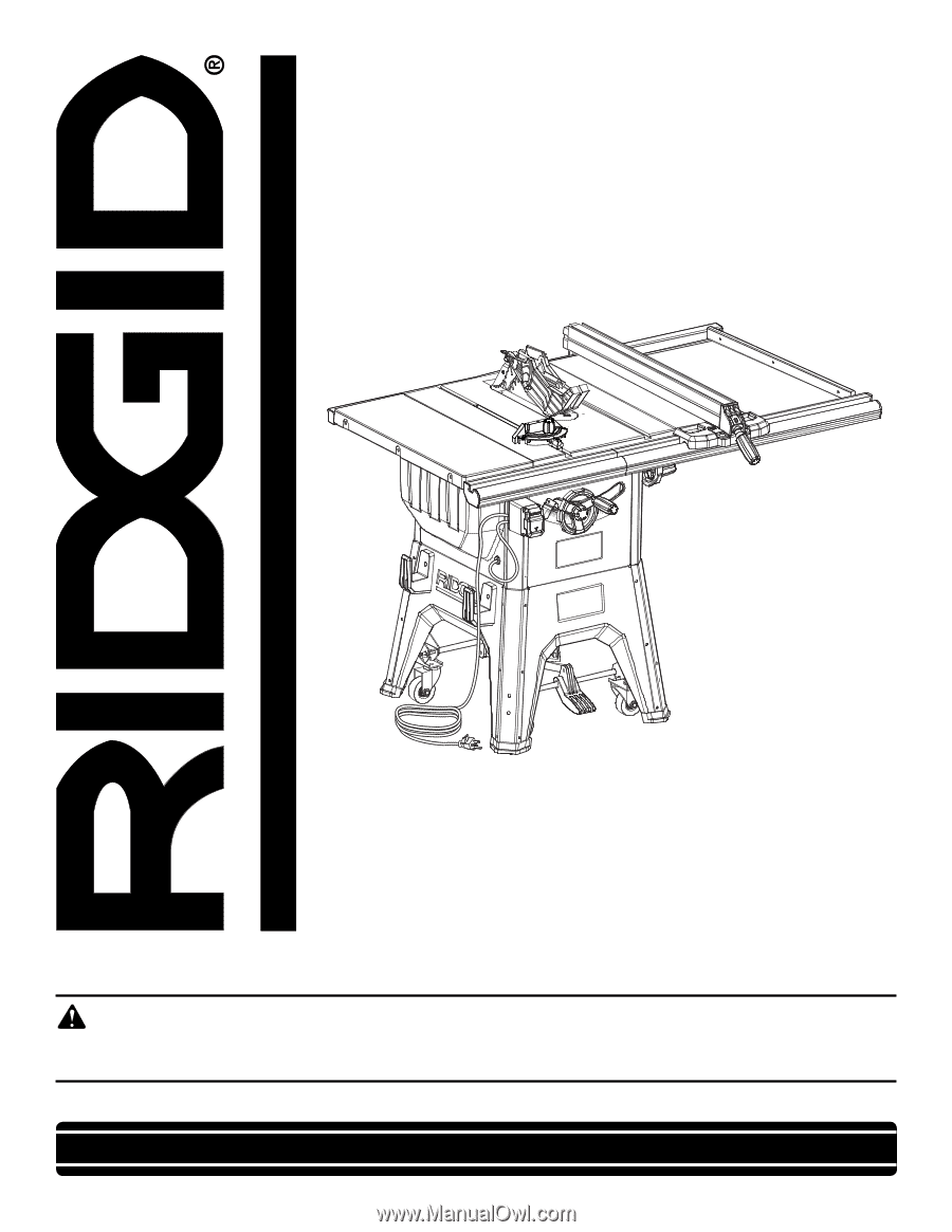
Your table saw has been engineered and manufactured to our high standards for dependability, ease of operation, and
operator safety. When properly cared for, it will give you years of rugged, trouble-free performance.
WARNING:
To reduce the risk of injury, the user must read and understand the operator’s manual before using this
product.
Thank you for buying a RIDGID
®
product.
OPERATOR’S MANUAL
10 in. TABLE SAW
R4512
SAVE THIS MANUAL FOR FUTURE REFERENCE
45