Ridgid R4512 Owners Manual - Page 35
To Set The Rip Fence Scale Indicator, To The Blade, To Use The Miter Gauge - dimensions
 |
View all Ridgid R4512 manuals
Add to My Manuals
Save this manual to your list of manuals |
Page 35 highlights
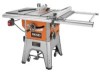
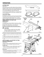
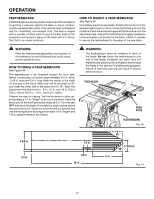
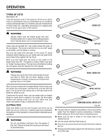
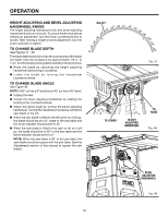
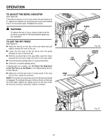
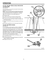
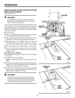
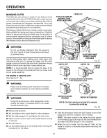
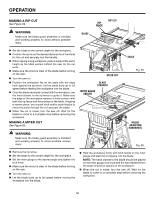
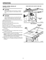
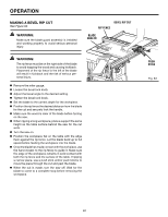
OPERATION To Set the rip fence Scale indicator to the Blade See Figure 52. Use the indicator on the rip fence to position the fence along the scale on the front rail. Note: The anti-kickback pawls and blade guard assembly must be removed to perform this adjustment. Reinstall the blade guard assembly when the adjustment is complete. Begin with the blade at a zero angle (straight up). Unplug the saw. Loosen the rip fence by lifting the locking handle. Set the rip fence gently against the blade tip edge. Loosen the screw on the scale indicator and align with the 0 mark as shown. Tighten the screw and check the dimension and the rip fence. Repeat this adjustment on the other side of the blade. TO use the miter gauge See Figure 53. The miter gauge provides greater accuracy in angled cuts. For very close tolerances, test cuts are recommended. There are two miter gauge grooves, one on either side of the blade. When making a 90° cross cut, you can use either miter gauge groove. When making a beveled cross cut (the blade tilted in relation to the table) the miter gauge should be located in the slot on the right so that the blade is tilted away from the miter gauge and your hands. The miter gauge can be turned 60° to the right or left. Loosen the lock knob. Pull out the stop pin and rotate the gauge until the desired angle is reached on the scale. Retighten the lock knob. screw Rip fence Blade Locking HANDLE Scale Front rail Fig. 52 LOCK KNOB MITER GAUGE Fig. 53 35
-
 1
1 -
2
-
3
-
4
-
5
-
6
-
7
-
8
-
9
-
10
-
11
-
12
-
13
-
14
-
15
-
16
-
17
-
18
-
19
-
20
-
21
-
22
-
23
-
24
-
25
-
26
-
27
-
28
-
29
-
 30
30 -
 31
31 -
 32
32 -
 33
33 -
 34
34 -
 35
35 -
 36
36 -
 37
37 -
 38
38 -
 39
39 -
 40
40 -
41
-
42
-
43
-
44
-
45
-
46
-
47
-
48
-
49
-
50
-
51
-
52
-
53
-
54
-
55
-
56
-
57
-
58
-
59
-
60
-
61
-
62
-
63
-
64
-
65
-
66
-
67
-
68
-
69
-
70
-
71
-
72
-
73
-
74
-
75
-
76
-
77
-
78
-
79
-
80
-
81
-
82
-
83
-
84
-
85
-
86
-
87
-
88
-
89
-
90
-
91
-
92
-
93
-
94
-
95
-
96
-
97
-
98
-
99
-
100
-
101
-
102
-
103
-
104
-
105
-
106
-
107
-
108
-
109
-
110
 |
 |
