Ridgid R4512 Owners Manual - Page 24
Installing The Rails Onto The Saw, Table - zero
 |
View all Ridgid R4512 manuals
Add to My Manuals
Save this manual to your list of manuals |
Page 24 highlights
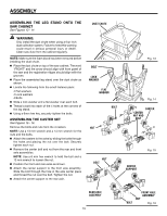
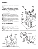
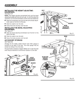
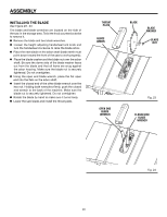
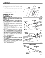
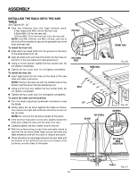
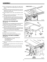
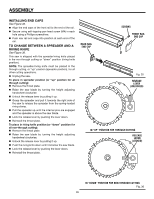
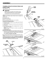
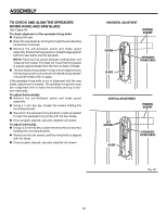
ASSEMBLY installing the rAILS onto the saw table See Figures 29 - 32. Take the following from the large fastener pack: 9 Hex head bolts (M8 x 30 for the front rail) 9 Bolts (M8 x 20 for the rear rail) 16 Nuts (M8: 10 for the front rail, 6 for the rear rail) NOTE: One M8 x 30 bolt, one M8 x 20 bolt, and four of the nuts will be needed to secure the spreader bar to the front and rear rails. To install the front rail: Slide eight hex head bolts into the groove on the back of the assembled front rail. Align the bolts with and insert the bolts into the holes on the front of the saw table and table extensions. Using a 13 mm wrench, tighten the four center nuts. Do not tighten completely. Tighten the four outer nuts. Do not tighten completely. To install the rear rail: Insert eight bolts into the holes on the back of the saw table and table extensions. NOTE: Position the rear rail with the slotted side on the bottom and the lip on the top and facing out. Using a 6 mm hex key, tighten the four center bolts. Do not tighten completely. Tighten the four outer nuts. Do not tighten completely. To check the table and rail position: Turn the height adjusting handwheel clockwise to raise the blade. Gently place the rip fence against the blade as shown. The mark on the right side indicator should be at zero on the rip scale. NOTE: Do not lock the rip fence handle at this point. If the rip fence indicator is not at zero, slightly loosen the bolts and nudge the rails until the mark is at zero. Carefully tighten the four center nuts for the rail. With the rip fence lying on top of the saw table, check to see that the rip fence slides freely across the table and table extension and will not catch or drag at any point. There should be an equal gap between the saw table and the bottom of the rip fence from the front to back of the rip fence, on both sides of the blade. hex nut hex head bolt rear rail bolt LIP RIP FENCE BLADE front rail Fig. 29 Fig. 30 SCREWS rip fence ZERO indicator SCALE Fig. 31 24
-
 1
1 -
2
-
3
-
4
-
5
-
6
-
7
-
8
-
9
-
10
-
11
-
12
-
13
-
14
-
15
-
16
-
17
-
18
-
 19
19 -
 20
20 -
 21
21 -
 22
22 -
 23
23 -
 24
24 -
 25
25 -
 26
26 -
 27
27 -
 28
28 -
 29
29 -
30
-
31
-
32
-
33
-
34
-
35
-
36
-
37
-
38
-
39
-
40
-
41
-
42
-
43
-
44
-
45
-
46
-
47
-
48
-
49
-
50
-
51
-
52
-
53
-
54
-
55
-
56
-
57
-
58
-
59
-
60
-
61
-
62
-
63
-
64
-
65
-
66
-
67
-
68
-
69
-
70
-
71
-
72
-
73
-
74
-
75
-
76
-
77
-
78
-
79
-
80
-
81
-
82
-
83
-
84
-
85
-
86
-
87
-
88
-
89
-
90
-
91
-
92
-
93
-
94
-
95
-
96
-
97
-
98
-
99
-
100
-
101
-
102
-
103
-
104
-
105
-
106
-
107
-
108
-
109
-
110
 |
 |
