Ridgid R4512 Owners Manual - Page 26
Installing End Caps, To Change Between A Spreader And A, Riving Knife - blade alignment
 |
View all Ridgid R4512 manuals
Add to My Manuals
Save this manual to your list of manuals |
Page 26 highlights
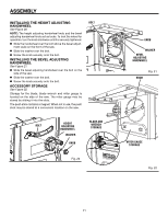
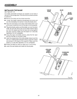
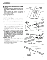
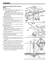
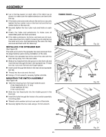
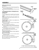
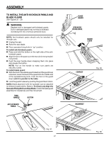
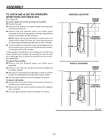
ASSEMBLY INSTALLING END CAPS See Figure 35. Align the end caps of the front rail to the end of the rail. Secure using self-tapping pan head screw (M4) in each hole using a Phillips screwdriver. Push rear rail end caps into position at each end of the rail. TO CHANGE BETWEEN A spreader AND A riving knife See Figure 36. This saw is shipped with the spreader/riving knife placed in the non-through cutting or "down" position (riving knife position). NOTE: The spreader/riving knife must be placed in the through cutting, or "up" position (spreader position), for all other cutting operations. Unplug the saw. To place in spreader position (or "up" position for all through cutting): Remove the throat plate. Raise the saw blade by turning the height adjusting handwheel clockwise. Unlock the release lever by pulling it up. Grasp the spreader and pull it towards the right side of the saw to release the spreader from the spring-loaded riving clamp. Pull the spreader up until the internal pins are engaged and the spreader is above the saw blade. Lock the release lever by pushing the lever down. Reinstall the throat plate. To place in riving knife position (or "down" position for all non-through cutting): Remove the throat plate. Raise the saw blade by turning the height adjusting handwheel clockwise. Unlock the release lever by pulling it up. Push the riving knife down until it is below the saw blade. Lock the release lever by pushing the lever down. Reinstall the throat plate. REAR RAIL end cap SCREWS Front rail end cap Fig. 35 release lever (UNLOCKED) in "UP" POSITION for through cutting release lever (LOCKED) in "down" position for non-through cutting Fig. 36 26
-
 1
1 -
2
-
3
-
4
-
5
-
6
-
7
-
8
-
9
-
10
-
11
-
12
-
13
-
14
-
15
-
16
-
17
-
18
-
19
-
20
-
 21
21 -
 22
22 -
 23
23 -
 24
24 -
 25
25 -
 26
26 -
 27
27 -
 28
28 -
 29
29 -
 30
30 -
 31
31 -
32
-
33
-
34
-
35
-
36
-
37
-
38
-
39
-
40
-
41
-
42
-
43
-
44
-
45
-
46
-
47
-
48
-
49
-
50
-
51
-
52
-
53
-
54
-
55
-
56
-
57
-
58
-
59
-
60
-
61
-
62
-
63
-
64
-
65
-
66
-
67
-
68
-
69
-
70
-
71
-
72
-
73
-
74
-
75
-
76
-
77
-
78
-
79
-
80
-
81
-
82
-
83
-
84
-
85
-
86
-
87
-
88
-
89
-
90
-
91
-
92
-
93
-
94
-
95
-
96
-
97
-
98
-
99
-
100
-
101
-
102
-
103
-
104
-
105
-
106
-
107
-
108
-
109
-
110
 |
 |
