Ridgid R4512 Owners Manual - Page 33
Height Adjusting And Bevel Adjusting, Handwheel Knobs, To Change Blade Depth, To Change Blade Angle - table saw manual
 |
View all Ridgid R4512 manuals
Add to My Manuals
Save this manual to your list of manuals |
Page 33 highlights
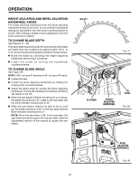
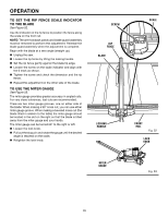
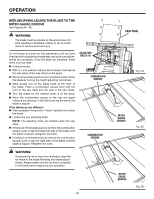
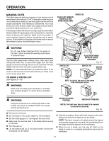
OPERATION height adjusting and bevel adjusting handwheel knobs The height adjusting handwheel knob and bevel adjusting handwheel knobs act as locks. To unlock either knob before making an adjustment, turn the knob counterclockwise to loosen. After making a height or bevel adjustment, turn the knob clockwise to tighten. TO CHANGE BLADE DEPTH See Figures 47 - 48. The blade depth should be set so the outer points of the blade are higher than the workpiece by approximately 1/8 in. to 1/4 in. but the lowest points (gullets) are below the top surface. Raise the blade by unlocking the height adjusting handwheel and turning it clockwise. Lower the blade by turning the handwheel counterclockwise. TO CHANGE BLADE ANGLE See Figure 49. Note: A 90° cut has a 0° bevel and a 45° cut has a 45° bevel. Unplug the saw. Unlock the bevel adjusting handwheel by rotating the locking knob counterclockwise. Adjust the bevel angle by turning the bevel adjusting handwheel. Turning the handwheel clockwise will tilt the saw blade to the left. When the saw blade is tilted to the left as far as it will go, the blade should be at a 45° angle to the saw table and the bevel indicator should point to 45°. When the saw blade is tilted to the right as far as it will go, the blade should be at 90° to the saw table and the bevel indicator should point to 0°. Note: When the saw blade is 90° to the saw table, the saw blade should be square with the saw table. (See the Adjustments section of this manual to square the saw blade.) GULLET Fig. 47 to lower HEIGHT adjusting handwheel to raise Fig. 48 BEVEL adjusting handwheel Fig. 49 33
-
 1
1 -
2
-
3
-
4
-
5
-
6
-
7
-
8
-
9
-
10
-
11
-
12
-
13
-
14
-
15
-
16
-
17
-
18
-
19
-
20
-
21
-
22
-
23
-
24
-
25
-
26
-
27
-
 28
28 -
 29
29 -
 30
30 -
 31
31 -
 32
32 -
 33
33 -
 34
34 -
 35
35 -
 36
36 -
 37
37 -
 38
38 -
39
-
40
-
41
-
42
-
43
-
44
-
45
-
46
-
47
-
48
-
49
-
50
-
51
-
52
-
53
-
54
-
55
-
56
-
57
-
58
-
59
-
60
-
61
-
62
-
63
-
64
-
65
-
66
-
67
-
68
-
69
-
70
-
71
-
72
-
73
-
74
-
75
-
76
-
77
-
78
-
79
-
80
-
81
-
82
-
83
-
84
-
85
-
86
-
87
-
88
-
89
-
90
-
91
-
92
-
93
-
94
-
95
-
96
-
97
-
98
-
99
-
100
-
101
-
102
-
103
-
104
-
105
-
106
-
107
-
108
-
109
-
110
 |
 |
