Ridgid R4512 Owners Manual - Page 25
Installing The Spreader Bar, Mounting The Switch Assembly - table saw parts
 |
View all Ridgid R4512 manuals
Add to My Manuals
Save this manual to your list of manuals |
Page 25 highlights
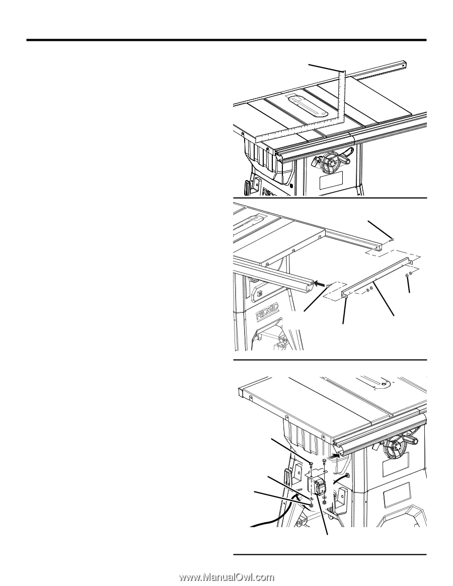
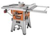
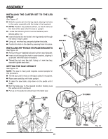
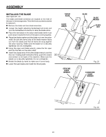
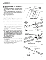
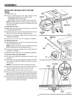
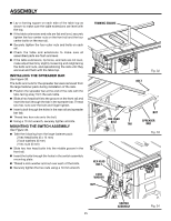
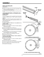
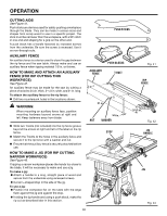
ASSEMBLY Lay a framing square on each side of the table top as shown to make sure the table extensions are level with the top. If the table extensions and rails are flat and level, securely tighten the four center nuts on the front rail and the four center bolts on the rear rail. Securely tighten the four outer nuts and bolts on each rail. Check the table and extensions to make sure all assembled parts are flush and level. If the table extensions, rip fence, and rails are not level, make adjustments by slightly loosening and retightening the bolts and nuts, and repositioning the rails until they are level and flush with the table top. INSTALLING THE SPreader BAR See Figure 33. The bolts and nuts for the spreader bar were removed from the large fastener pack during installation of the rails. Position the spreader bar at the end of the rails with the tabs facing away from the saw table. Slide a hex head bolt into the groove on the front rail and insert the bolt through the tab in the spreader bar. Thread two hex nuts over the bolt and finger tighten. Insert a bolt through the holes in the rear rail and spreader bar tab. Thread two hex nuts onto the bolt. Using a 13 mm wrench, securely tighten all bolts. MOUNTING THE SWITCH ASSEMBLY See Figure 34. Take the following from the large fastener pack: 2 hex head bolts (6 x 14 mm) 2 lock washers (6 mm) 2 hex nuts (6 mm) Slide two hex head bolts into the middle groove in the front rail. Insert the bolts through the holes in the switch assembly mounting plate. Thread a lock washer and nut over each of the bolts. Securely tighten the hex nuts using a 10 mm wrench. framing square HEX HEAD BOLT HEX HEAD BOLT lock washer nut 45 bolt Fig. 32 nut sPREADER TAB bar Fig. 33 switch assembly Fig. 34 25
-
 1
1 -
2
-
3
-
4
-
5
-
6
-
7
-
8
-
9
-
10
-
11
-
12
-
13
-
14
-
15
-
16
-
17
-
18
-
19
-
 20
20 -
 21
21 -
 22
22 -
 23
23 -
 24
24 -
 25
25 -
 26
26 -
 27
27 -
 28
28 -
 29
29 -
 30
30 -
31
-
32
-
33
-
34
-
35
-
36
-
37
-
38
-
39
-
40
-
41
-
42
-
43
-
44
-
45
-
46
-
47
-
48
-
49
-
50
-
51
-
52
-
53
-
54
-
55
-
56
-
57
-
58
-
59
-
60
-
61
-
62
-
63
-
64
-
65
-
66
-
67
-
68
-
69
-
70
-
71
-
72
-
73
-
74
-
75
-
76
-
77
-
78
-
79
-
80
-
81
-
82
-
83
-
84
-
85
-
86
-
87
-
88
-
89
-
90
-
91
-
92
-
93
-
94
-
95
-
96
-
97
-
98
-
99
-
100
-
101
-
102
-
103
-
104
-
105
-
106
-
107
-
108
-
109
-
110
 |
 |