Ridgid R4512 Owners Manual - Page 23
Installing/removing The Throat Plate, Assembling The Rails
 |
View all Ridgid R4512 manuals
Add to My Manuals
Save this manual to your list of manuals |
Page 23 highlights
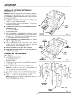
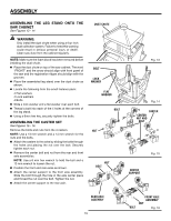
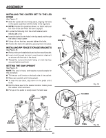
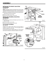
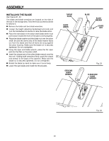
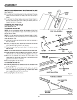
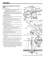
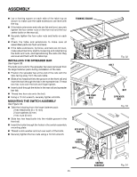
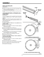
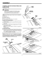
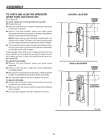
ASSEMBLY INSTALLING/REMOVing the THROAT PLATE See Figure 25. To install the throat plate, slip the tab underneath the saw table at the back of the saw and push down to secure in place. To remove the throat plate, place your index finger in the hole and lift the front end, pulling the throat plate out toward the front of the saw. ASSEMBLING THE RAILS See Figures 26 - 28. To assemble the front rail: NOTE: Do not completely tighten set screws until all front rail pieces are assembled and you have made sure the rail will lie flat and level. NOTE: Front rail sections have a rip scale printed on them. In the illustrations, rail connector bars are inserted into the long rail section first. Insert half of each rail connector bar into the grooves in the rail sections. Using a 3 mm hex key, attach the connector bar to the rail by partially tightening the set screws. Attach a second rail connector bar in the same way as the first one. NOTE: The left side rail section is shorter than the right side. Slide the second front rail section onto the first, over the attached rail connector bars. Partially tighten set screws. Place the assembled rail sections on a flat surface and make sure the rail lies flat and level. There should be no gaps between the two sections. Securely tighten all set screws. To assemble the rear rail: Slide the remaining rail connector bar into the slot in the a rear rail section. Assemble the rear rail sections in the same way as the front rail. Make sure the rail lies flat and level and there are no gaps between the two sections. Securely tighten all set screws. BLADE THROAT PLATE FRONT RAIL ASSEMBLY Rail connector bar RIP scale Fig. 25 LONG RAIL SECTION HEX KEY SET SCREWS Rail connector bar Fig. 26 FRONT RAIL sections SHORT RAIL SECTION Rail connector bar Fig. 27 Rear rail ASSEMBLY RAIL CONNECTOR BAR Rear rail SECTIONS 23 Fig. 28
-
 1
1 -
2
-
3
-
4
-
5
-
6
-
7
-
8
-
9
-
10
-
11
-
12
-
13
-
14
-
15
-
16
-
17
-
 18
18 -
 19
19 -
 20
20 -
 21
21 -
 22
22 -
 23
23 -
 24
24 -
 25
25 -
 26
26 -
 27
27 -
 28
28 -
29
-
30
-
31
-
32
-
33
-
34
-
35
-
36
-
37
-
38
-
39
-
40
-
41
-
42
-
43
-
44
-
45
-
46
-
47
-
48
-
49
-
50
-
51
-
52
-
53
-
54
-
55
-
56
-
57
-
58
-
59
-
60
-
61
-
62
-
63
-
64
-
65
-
66
-
67
-
68
-
69
-
70
-
71
-
72
-
73
-
74
-
75
-
76
-
77
-
78
-
79
-
80
-
81
-
82
-
83
-
84
-
85
-
86
-
87
-
88
-
89
-
90
-
91
-
92
-
93
-
94
-
95
-
96
-
97
-
98
-
99
-
100
-
101
-
102
-
103
-
104
-
105
-
106
-
107
-
108
-
109
-
110
 |
 |
