Ridgid R4512 Owners Manual - Page 20
Installing The Caster Set To The Leg, Stand, Installing Rip Fence Storage Brackets, Setting The Saw - insert
 |
View all Ridgid R4512 manuals
Add to My Manuals
Save this manual to your list of manuals |
Page 20 highlights
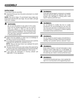
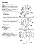
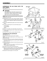
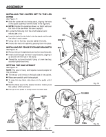
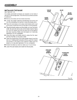
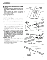
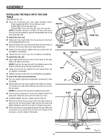
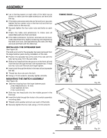
ASSEMBLY INSTALLING THE CASTER SET TO THE LEG STAND See Figure 17. Slide the caster set into the leg stand, aligning the holes in the caster assembly with the holes in the leg stand. NOTE: Position the pedal as shown, so that it will be in the front of the saw when the saw is upright. Locate the following from the small fastener pack: 8 Bolts (M8 x 16) Insert the bolts into the holes in the leg stand and through the holes in each caster. Using a 5 mm hex key, securely tighten the bolts. Position the feet on the stand by pressing them into place. INSTALLING RIP FENCE STORAGE BRACKETS See Figure 18. Remove the pre-installed bolt and nut from each bracket. Insert a bolt through the hole in each bracket, aligning it as shown with the hole in the stand. Thread the nut over the bolt. Using a 5 mm hex key, securely tighten each bolt. SETTING THE SAW UPRIGHT See Figure 19. NOTE: The saw is heavy and requires several people for this procedure. Tilt the saw until it rests on the back side of the cabinet. Raise saw carefully until it sits upright. To raise the saw table, step down on the pedal until it locks. Roll the table saw to the desired location making sure the surface is firm and level. Pull up on the pedal to slowly lower the table saw. CASTER SET feet NUT BRACKET BOLT Fig. 18 to lower Socket head BOLT Fig. 17 20 PEDAL Fig. 19
-
 1
1 -
2
-
3
-
4
-
5
-
6
-
7
-
8
-
9
-
10
-
11
-
12
-
13
-
14
-
 15
15 -
 16
16 -
 17
17 -
 18
18 -
 19
19 -
 20
20 -
 21
21 -
 22
22 -
 23
23 -
 24
24 -
 25
25 -
26
-
27
-
28
-
29
-
30
-
31
-
32
-
33
-
34
-
35
-
36
-
37
-
38
-
39
-
40
-
41
-
42
-
43
-
44
-
45
-
46
-
47
-
48
-
49
-
50
-
51
-
52
-
53
-
54
-
55
-
56
-
57
-
58
-
59
-
60
-
61
-
62
-
63
-
64
-
65
-
66
-
67
-
68
-
69
-
70
-
71
-
72
-
73
-
74
-
75
-
76
-
77
-
78
-
79
-
80
-
81
-
82
-
83
-
84
-
85
-
86
-
87
-
88
-
89
-
90
-
91
-
92
-
93
-
94
-
95
-
96
-
97
-
98
-
99
-
100
-
101
-
102
-
103
-
104
-
105
-
106
-
107
-
108
-
109
-
110
 |
 |
