Ridgid R4512 Owners Manual - Page 46
To Set The Blade At 0° And 45° - table saw extension table
 |
View all Ridgid R4512 manuals
Add to My Manuals
Save this manual to your list of manuals |
Page 46 highlights
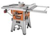
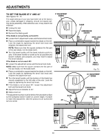
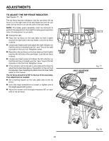
adjustments TO SET the blade at 0° and 45° See Figures 73 - 74. The angle settings of your saw have been set at the factory and, unless damaged in shipping, should not require setting during assembly. After extensive use, it may need to be checked. Unplug the saw. Raise the blade. Remove the blade guard. If the blade is not perfectly vertical (0°): Loosen the 0º adjustment screw and the bevel lock knob. Place a combination square beside the blade on the left. Lock the angle by tightening the bevel lock knob and retighten the adjustment bolt. NOTE: Make sure that the square contacts the flat part of the saw blade, not the blade teeth. Turn the bevel handle until the bevel indicator points to zero. If the bevel handle is turned as far as possible and doesn't indicate zero properly, you may need to adjust the bevel indicator. If the blade is not an exact 45°: Loosen the adjustment screw and the bevel lock knob. NOTE: Make sure that the square contacts the flat part of the saw blade, not the blade teeth. Place a combination square beside the blade on the left. Lock the angle by tightening the bevel lock knob and retighten the adjustment bolt. Turn the bevel handle until the bottom of the blade has moved completely to the left side of the slot. Lock the angle by tightening the bevel lock knob. If the blade is not an exact 45°, loosen the adjustment bolt and the bevel lock knob. Adjust the bevel indicator to 45°. Make a test cut. The adjustment screws must be below the saw table surface so the workpiece doesn't catch on uneven edges. If unable to make this adjustment, take the product to an authorized service center. 0° ADJUSTMENT screw BEVEL INDICATOR BLADE 45° BLADE COMBINATION SQUARE BEVEL LOCK knob BEVEL handle Fig. 73 45° ADJUSTMENT SCREW COMBINATION SQUARE BEVEL LOCK knob BEVEL INDICATOR 46 BEVEL HANDLE Fig. 74
-
 1
1 -
2
-
3
-
4
-
5
-
6
-
7
-
8
-
9
-
10
-
11
-
12
-
13
-
14
-
15
-
16
-
17
-
18
-
19
-
20
-
21
-
22
-
23
-
24
-
25
-
26
-
27
-
28
-
29
-
30
-
31
-
32
-
33
-
34
-
35
-
36
-
37
-
38
-
39
-
40
-
 41
41 -
 42
42 -
 43
43 -
 44
44 -
 45
45 -
 46
46 -
 47
47 -
 48
48 -
 49
49 -
 50
50 -
 51
51 -
52
-
53
-
54
-
55
-
56
-
57
-
58
-
59
-
60
-
61
-
62
-
63
-
64
-
65
-
66
-
67
-
68
-
69
-
70
-
71
-
72
-
73
-
74
-
75
-
76
-
77
-
78
-
79
-
80
-
81
-
82
-
83
-
84
-
85
-
86
-
87
-
88
-
89
-
90
-
91
-
92
-
93
-
94
-
95
-
96
-
97
-
98
-
99
-
100
-
101
-
102
-
103
-
104
-
105
-
106
-
107
-
108
-
109
-
110
 |
 |
