Ridgid R4512 Owners Manual - Page 19
Assembling The Leg Stand Onto The, Saw Cabinet, Warning, Assembling The Caster Set - dust collection
 |
View all Ridgid R4512 manuals
Add to My Manuals
Save this manual to your list of manuals |
Page 19 highlights
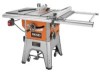
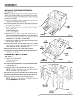
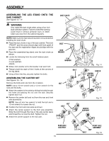
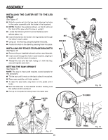
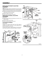
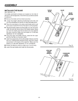
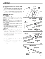
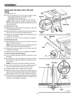
ASSEMBLY ASSEMBLING THE LEG stand onto the saw CABINET See Figures 13 - 14. WARNING: Only install the dust chute when using a four inch dust collection system. Failure to heed this warning could result in serious personal injury or death. Clean saw dust from the cabinet regularly. NOTE: Make sure the foam block has been removed before installing the dust chute. Place the dust chute on top of the saw cabinet. The word "FRONT" and the arrow should align with front panel of the saw and the registration ridges should align with the grooves. Place the assembled leg stand over the dust chute as shown. Locate the following from the small fastener pack: 4 Flat washers 4 Lock washers 4 Bolts Slide a lock washer and a flat washer over each bolt. Thread a bolt into each of the 4 holes at the corners of the leg stand. Using a 6mm hex key, securely tighten the bolts. ASSEMBLING THE CASTER SET See Figures 15 - 16. Remove the bolts and nuts from the 4 casters. NOTE: Use a 13 mm wrench and a 14 mm wrench for the nuts and the bolts. Attach the casters to the axles by sliding the bolts through the holes and placing the nut over the bolt. Securely tighten each nut. Remove the center bolt and nut from the rear and front axle assemblies. NOTE: Use a 6 mm hex wrench to hold the bolt and a 13 mm wrench to loosen the nut. Position the front and rear axles as shown. Attach the center support to the front axle assembly. Slide the bolt through the hole in the axle center piece and thread the nut over the bolt. Tighten the nut. Attach the center support to the rear axle. Dust chute BOLT lOCK washer flat washer BOLT NUT NUT BOLT Fig. 13 Fig. 14 CASTER CENTER NUT AND BOLT Fig. 15 CENTER SUPPORT REAR AXLE assembly 19 BOLT FRONT AXLE assembly NUT Fig. 16
-
 1
1 -
2
-
3
-
4
-
5
-
6
-
7
-
8
-
9
-
10
-
11
-
12
-
13
-
 14
14 -
 15
15 -
 16
16 -
 17
17 -
 18
18 -
 19
19 -
 20
20 -
 21
21 -
 22
22 -
 23
23 -
 24
24 -
25
-
26
-
27
-
28
-
29
-
30
-
31
-
32
-
33
-
34
-
35
-
36
-
37
-
38
-
39
-
40
-
41
-
42
-
43
-
44
-
45
-
46
-
47
-
48
-
49
-
50
-
51
-
52
-
53
-
54
-
55
-
56
-
57
-
58
-
59
-
60
-
61
-
62
-
63
-
64
-
65
-
66
-
67
-
68
-
69
-
70
-
71
-
72
-
73
-
74
-
75
-
76
-
77
-
78
-
79
-
80
-
81
-
82
-
83
-
84
-
85
-
86
-
87
-
88
-
89
-
90
-
91
-
92
-
93
-
94
-
95
-
96
-
97
-
98
-
99
-
100
-
101
-
102
-
103
-
104
-
105
-
106
-
107
-
108
-
109
-
110
 |
 |
