Ridgid R4512 Owners Manual - Page 21
Installing The Height Adjusting, Handwheel, Installing The Bevel Adjusting, Accessory Storage
 |
View all Ridgid R4512 manuals
Add to My Manuals
Save this manual to your list of manuals |
Page 21 highlights
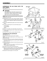
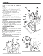
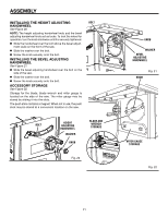
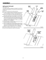
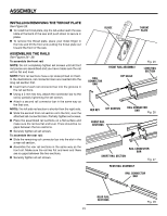
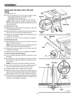
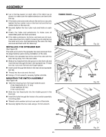
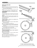
ASSEMBLY INSTALLING the HEIGHT ADJUSTING HANDWHEEL See Figure 20. NOTE: The height adjusting handwheel knob and the bevel adjusting handwheel knob act as locks. To lock the wheel for operation, turn the knob clockwise until it is securely tightened. Slide the handwheel over the bolt above the bevel adjustment scale on the front of the saw. Slide the washer over the bolt. Screw the knob securely onto the bolt. INSTALlING the BEVEL ADJUSTING HANDWHEEL See Figure 21. Slide the bevel adjusting handwheel over the bolt on the side of the saw. Slide the washer over the bolt. Screw the knob securely onto the bolt. ACCESSORY STORAGE See Figure 22. Storage for the blade, blade wrench and miter gauge is located on the side of the saw. The miter gauge may be stored by sliding it into the slots. The push stick contains a magnet. When not in use, the push stick may be stored at a convenient location on the saw. bolt bolt HEIGHT ADJUSTING HANDWHEEL WASHER knob BLADE AND WRENCH storage Fig. 20 knob WASHER BEVEL ADJUSTING HANDWHEEL knob Fig. 21 miter gauge storage Fig. 22 21
-
 1
1 -
2
-
3
-
4
-
5
-
6
-
7
-
8
-
9
-
10
-
11
-
12
-
13
-
14
-
15
-
 16
16 -
 17
17 -
 18
18 -
 19
19 -
 20
20 -
 21
21 -
 22
22 -
 23
23 -
 24
24 -
 25
25 -
 26
26 -
27
-
28
-
29
-
30
-
31
-
32
-
33
-
34
-
35
-
36
-
37
-
38
-
39
-
40
-
41
-
42
-
43
-
44
-
45
-
46
-
47
-
48
-
49
-
50
-
51
-
52
-
53
-
54
-
55
-
56
-
57
-
58
-
59
-
60
-
61
-
62
-
63
-
64
-
65
-
66
-
67
-
68
-
69
-
70
-
71
-
72
-
73
-
74
-
75
-
76
-
77
-
78
-
79
-
80
-
81
-
82
-
83
-
84
-
85
-
86
-
87
-
88
-
89
-
90
-
91
-
92
-
93
-
94
-
95
-
96
-
97
-
98
-
99
-
100
-
101
-
102
-
103
-
104
-
105
-
106
-
107
-
108
-
109
-
110
 |
 |
