Ridgid R4512 Owners Manual - Page 18
Installing The Table Extensions, Assembling The Leg Stand - 10 inch
 |
View all Ridgid R4512 manuals
Add to My Manuals
Save this manual to your list of manuals |
Page 18 highlights
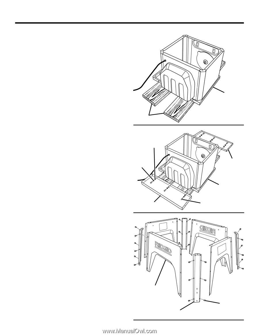
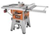
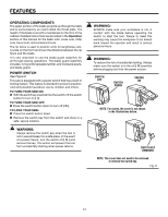
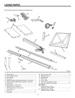
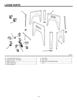
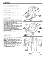
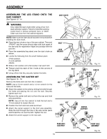
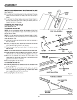
ASSEMBLY INSTALLING THE TABLE EXTENSIONS See Figures 10 - 11. NOTE: It is helpful to place two inch-thick boards on the floor before lifting the saw table and motor housing from the box. This will make it easier to assemble parts, and to move the saw and set it upright. Lift the saw table and motor housing from the box and position it on the boards as shown. Loosen the plastic wrap from the table and lift each side to remove the wrapping. From the large fastener pack, locate the following parts: 6 Bolts (M10 x 25) 6 Lock washers (M10) 6 Flat washers (M10) With the table saw in the upside down position, place a table extension against the table top, on the same side as the power cord. The larger holes in the extension should be aligned with the holes in the saw table. Make sure the edges of the table extensions are aligned with the edges of the table. Insert a lock washer and flat washer over a bolt. Thread the bolt into the holes in the table extension and saw table. Repeat for the two remaining holes. Repeat above step on the other table extension. Using an 8 mm socket, tighten the socket head bolts. Do not tighten completely. ASSEMBLING THE LEG stand See Figure 12. Locate the following parts: 4 Leg stand sections 4 Outer corners From the small fastener pack, locate the following parts: 24 Bolts (M6 x 10) Place an outer corner outside a leg stand section. NOTE: The top of the outer corner has a bent tab and hole for assembly to the saw cabinet. Insert a bolt into each of the three holes and finger tighten. Repeat with remaining corners and leg stand sections. Using a 4 mm hex key, tighten all bolts securely. NOTE: The front of the stand is the section with the English WARNING label attached. BOARDS flat washer lOCK washer TABLE EXTENSION LEG STAND SECTION outer cORNER 18 saw TABLE Fig. 10 TABLE EXTENSION saw TABLE BOLT Fig. 11 BOLT Fig. 12
-
 1
1 -
2
-
3
-
4
-
5
-
6
-
7
-
8
-
9
-
10
-
11
-
12
-
 13
13 -
 14
14 -
 15
15 -
 16
16 -
 17
17 -
 18
18 -
 19
19 -
 20
20 -
 21
21 -
 22
22 -
 23
23 -
24
-
25
-
26
-
27
-
28
-
29
-
30
-
31
-
32
-
33
-
34
-
35
-
36
-
37
-
38
-
39
-
40
-
41
-
42
-
43
-
44
-
45
-
46
-
47
-
48
-
49
-
50
-
51
-
52
-
53
-
54
-
55
-
56
-
57
-
58
-
59
-
60
-
61
-
62
-
63
-
64
-
65
-
66
-
67
-
68
-
69
-
70
-
71
-
72
-
73
-
74
-
75
-
76
-
77
-
78
-
79
-
80
-
81
-
82
-
83
-
84
-
85
-
86
-
87
-
88
-
89
-
90
-
91
-
92
-
93
-
94
-
95
-
96
-
97
-
98
-
99
-
100
-
101
-
102
-
103
-
104
-
105
-
106
-
107
-
108
-
109
-
110
 |
 |