Samsung 570DX User Manual (user Manual) (ver.1.0) (English) - Page 6
Connection Panel
 |
UPC - 729507801155
View all Samsung 570DX manuals
Add to My Manuals
Save this manual to your list of manuals |
Page 6 highlights
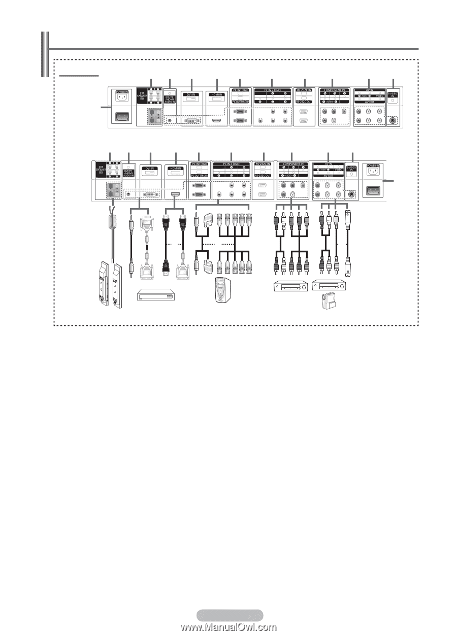
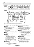
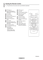
Connection Panel Rear Panel PPM50M7F 1 23 4 5 6 7 89 0! PPM63M7F 23 4 5 6 7 89 0! 1 or or or ➢ The product color and shape may vary depending on the model. ☛ Whenever you connect an audio or video system to your set, ensure that all elements are switched off. When connecting an external device, match the color of the connection terminal to the cable. 1 POWER IN Connect the supplied power cord. 2 EXT SPEAKER (8Ω) Connect external speakers. 3 DVI/PC/HDMI AUDIO IN Connect to the audio output jack on your PC or DVI component. ➢ AUDIO is an audio input jack for PC1 and PC2 modes. 4 DVI IN Connect to the video output jack for device with DVI output. 5 HDMI IN Connect to the video output jack of a device with DVI output. -This input can also be used as a DVI connection with separate analog audio inputs. An optional HDMI/DVI cable will be necessary to make this connection. -When using an optional HDMI/DVI adapter, the DVI analog audio inputs on your PDP Display allow you to receive left and right audio from your DVI device. 6 PC IN1/PC OUT1 - PC IN1: Connect to the video output jack on your PC. - PC OUT1: Connect to the video input jack on external devices (such as another display). 7 PC IN2 (BNC) Connect for RGB HV video signal input from a PC. ➢ "PC Mode" from this page onward means PC1/PC2 mode using RGB1(PC1) and RGB2(PC2). 8 RS-232C - IN: Used for the MDC (Multi-Display Control) function when connecting the PC or RS232C output of another PDP Display. - OUT: Used for the MDC function when connecting with the RS-232C input of another PDP Display. ➢ For further details about connections, refer to Page 10. 9 COMPONENT IN Video (Y/PB/PR) and audio (L/R) inputs for Component connections. 0 AV (VIDEO/AUDIO L/R) - IN: Video and audio inputs for external devices, such as a camcorder or VCR. - OUT: Outputs for external devices. ! S-VIDEO IN Video input for external devices with an S-Video output, such as a camcorder or VCR. English - 6
-
 1
1 -
 2
2 -
 3
3 -
 4
4 -
 5
5 -
 6
6 -
 7
7 -
 8
8 -
 9
9 -
 10
10 -
 11
11 -
 12
12 -
13
-
14
-
15
-
16
-
17
-
18
-
19
-
20
-
21
-
22
-
23
-
24
-
25
-
26
-
27
-
28
-
29
-
30
-
31
-
32
-
33
-
34
-
35
-
36
-
37
-
38
-
39
-
40
 |
 |