Sharp HT-X1 HT-X1 Operation Manual - Page 20
Preparation for Use
 |
UPC - 074000366138
View all Sharp HT-X1 manuals
Add to My Manuals
Save this manual to your list of manuals |
Page 20 highlights
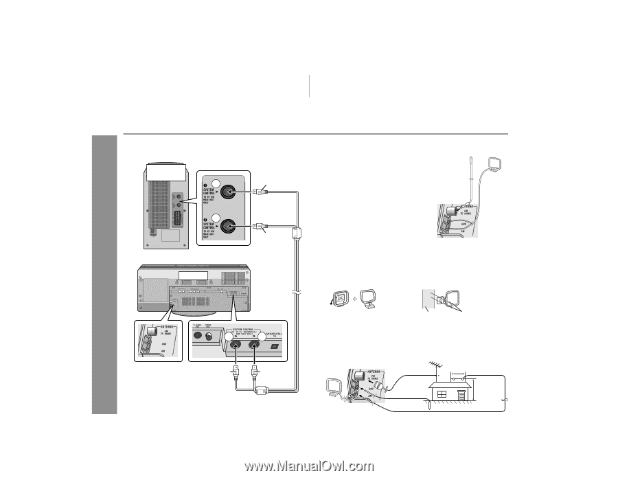
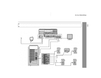
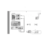
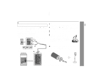
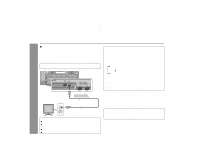
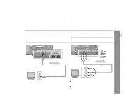
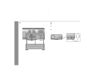
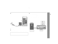
HT-X1 System connections (continued) " Connecting the system connection cable Connect the main unit and subwoofer/amplifier unit as follows. Subwoofer/ amplifier unit 1 Black 2 Blue Main unit " Antenna connection Supplied FM antenna: Connect the FM antenna wire to the FM 75 OHMS jack and position the FM antenna wire in the direction where the strongest signal can be received. Supplied AM loop antenna: Connect the AM loop antenna wire to the AM and GND terminals. Position the AM loop antenna for optimum reception. Place the AM loop antenna on a shelf, etc., or attach it to a stand or a wall with screws (not supplied). FM antenna AM loop antenna Note: Placing the antenna on the system or near the AC power cord may cause noise pickup. Place the antenna away from the system for better reception. Installing the AM loop antenna: < Assembling > < Attaching to the wall > Preparation for Use Antenna terminals 2 1 Blue Black 20 Wall Screws (not supplied) Outdoor FM or AM antenna: Use an outdoor FM or AM antenna if you require better reception. Consult your dealer. When using an outdoor AM antenna, be sure to keep the wire of the AM loop antenna connected. AM loop antenna Outdoor FM antenna Outdoor AM antenna 49 feet (15 m) Ground wire Ground rod 25 feet (7.5 m )
-
 1
1 -
2
-
3
-
4
-
5
-
6
-
7
-
8
-
9
-
10
-
11
-
12
-
13
-
14
-
 15
15 -
 16
16 -
 17
17 -
 18
18 -
 19
19 -
 20
20 -
 21
21 -
 22
22 -
 23
23 -
 24
24 -
 25
25 -
26
-
27
-
28
-
29
-
30
-
31
-
32
-
33
-
34
-
35
-
36
-
37
-
38
-
39
-
40
-
41
-
42
-
43
-
44
-
45
-
46
-
47
-
48
-
49
-
50
-
51
-
52
-
53
-
54
-
55
-
56
-
57
-
58
-
59
-
60
-
61
-
62
-
63
-
64
-
65
-
66
-
67
-
68
 |
 |