Sony CCD TRV16 Service Manual - Page 100
IRIS IN/OUT Adjustment, Note 1, MAX GAIN Adjustment
 |
UPC - 027242551497
View all Sony CCD TRV16 manuals
Add to My Manuals
Save this manual to your list of manuals |
Page 100 highlights
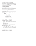
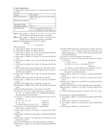
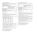
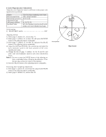
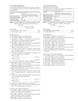
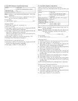
7. IRIS IN/OUT Adjustment For the unit to judge if the white balance is indoors or outdoors in auto white balance operations, measure the light level and write it in the EEPROM. If the level is not correct, the white balance will not be accurate. Subject Measurement Point Measuring Instrument Adjustment Page Adjustment Address Clear chart (Color bar standard picture frame) DDS display of LCD or TV monitor (Note 1) F 3C, 3D Note 1: The right four digits of the display data at the right bottom side of the LCD and TV monitor is the LIGHT LEVEL data. 00 XX XX n Lower two digits n Upper two digits Switch setting: 1) STEADY SHOT (Menu display OFF 2) NIGHT SHOT switch OFF Adjusting method: 1) Select page: 0, address: 01, and set data: 01. 2) Select page: 0, address: 03, and set data: 06. 3) Select page: D, address: 11, and set data: 02, and press the PAUSE button of the adjusting remote commander. 4) Select page: 2, address: 40, and set data: 02. 5) Select page: 2, address: 01, set data: 0B, and press the PAUSE button of the adjusting remote commander. 6) Read the DDS display data (Note 1), and take the upper two digits as D1 and the lower two as D2. 7) Convert D1 to decimal notation, and obtain D1'. (Refer to Table 5-1-2. "Hexadecimal notation - decimal notation conversion table" of "Service mode".) 8) Calculate D3' using the following equations. (Equations 1 and 2 are for decimal notation calculation). When D2 D0 D3' = D1' - 21 Equation 1 When D2 < D0 D3' = D1' - 22 Equation 2 9) Convert D3' to hexadecimal notation, and obtain D3. 10) Select page: F, address: 3C, set data: D3, and press the PAUSE button of the adjusting remote commander. 11) Select page: 2, address: 01, set data: 09, and press the PAUSE button of the adjusting remote commander. 12) Read the DDS display data (Note 1), and take the upper two digits as D4 and the lower two as D5. 13) Convert D4 to decimal notation, and obtain D4'. (Refer to Table 5-1-2. "Hexadecimal notation - decimal notation conversion table".) 14) Calculate D6' using the following equations. (Equations 3 and 4 are for decimal notation calculation). When D5 F0 D6' = D4' - 13 Equation 3 When D5 < F0 D6' = D4' - 14 Equation 4 15) Convert D6' to hexadecimal notation, and obtain D6. 16) Select page: F, address: 3D, set data: D6, and press the PAUSE button of the adjusting remote commander. Processing after Completing Adjustments 1) Select page: D, address: 11, and set data: 00, and press the PAUSE button of the adjusting remote commander. 2) Select page: 0, address: 01, and set data: 00. 3) Select page: 2, address: 01, and set data: 00, and press the PAUSE button of the adjusting remote commander. 4) Select page: 2, address: 40, and set data: 00. 5) Select page: 0, address: 03, and set data: 00. 8. MAX GAIN Adjustment Setting the minimum illumination. If it is not consistent, the image level required for taking subjects in low illuminance will not be produced (dark). Subject Measurement Point Measuring Instrument Adjustment Page Adjustment Address Specified Value Clear chart (Color bar standard picture frame) DDS display of LCD or TV monitor (Note 1) F 31 C0 to FF Note 1: The right two digits of the display data at the right bottom side of the LCD and TV monitor is the object data. 00 00 XX n Object data Switch setting: 1) STEADY SHOT (Menu display OFF 2) NIGHT SHOT switch OFF Adjusting method: 1) Select page: 0, address: 01, and set data: 01. 2) Select page: D, address: 11, and set data: 02, and press the PAUSE button of the adjusting remote commander. 3) Select of page: 0, address: 03, and set data: 01. 4) Select page: 2, address: 40, and set data: 02. 5) Select page: 2, address: 56, and set data: 40. 6) Select page: 2, address: 01, set data: 19, and press the PAUSE button of the adjusting remote commander. 7) Select page: F, address: 31, set data: 18, and press the PAUSE button of the adjusting remote commander. 8) Check that the DDS display data (Note 1) lies within the speci- fied value. Processing after Completing Adjustments 1) Select page: D, address: 11, and set data: 00, and press the PAUSE button of the adjusting remote commander. 2) Select page: 0, address: 01, and set data: 00. 3) Select page: 2, address: 01, and set data: 00, and press the PAUSE button of the adjusting remote commander. 4) Select page: 2, address: 40, and set data: 00. 5) Select page: 2, address: 56, and set data: 00. 6) Select page: 0, address: 03, and set data: 00.
-
 1
1 -
2
-
3
-
4
-
5
-
6
-
7
-
8
-
9
-
10
-
11
-
12
-
13
-
14
-
15
-
16
-
17
-
18
-
19
-
20
-
21
-
22
-
23
-
24
-
25
-
26
-
27
-
28
-
29
-
30
-
31
-
32
-
33
-
34
-
35
-
36
-
37
-
38
-
39
-
40
-
41
-
42
-
43
-
44
-
45
-
46
-
47
-
48
-
49
-
50
-
51
-
52
-
53
-
54
-
55
-
56
-
57
-
58
-
59
-
60
-
61
-
62
-
63
-
64
-
65
-
66
-
67
-
68
-
69
-
70
-
71
-
72
-
73
-
74
-
75
-
76
-
77
-
78
-
79
-
80
-
81
-
82
-
83
-
84
-
85
-
86
-
87
-
88
-
89
-
90
-
91
-
92
-
93
-
94
-
 95
95 -
 96
96 -
 97
97 -
 98
98 -
 99
99 -
 100
100 -
 101
101 -
 102
102 -
 103
103 -
 104
104 -
 105
105 -
106
-
107
-
108
-
109
-
110
-
111
-
112
-
113
-
114
-
115
-
116
-
117
-
118
-
119
-
120
-
121
-
122
-
123
-
124
-
125
-
126
-
127
-
128
-
129
-
130
-
131
-
132
-
133
-
134
-
135
-
136
-
137
-
138
-
139
-
140
-
141
-
142
-
143
-
144
-
145
-
146
-
147
-
148
-
149
-
150
-
151
-
152
-
153
-
154
-
155
-
156
-
157
-
158
-
159
-
160
-
161
-
162
-
163
-
164
-
165
-
166
-
167
-
168
-
169
-
170
-
171
-
172
-
173
-
174
-
175
-
176
-
177
 |
 |
