Sony CCD TRV16 Service Manual - Page 102
White Balance Check
 |
UPC - 027242551497
View all Sony CCD TRV16 manuals
Add to My Manuals
Save this manual to your list of manuals |
Page 102 highlights
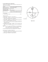
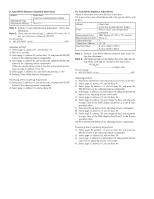
11. White Balance Check Subject Filter Measurement Point Measuring Instrument Specified Value Clear chart (Color bar standard picture frame) Filter C14 for color temperature correction ND filter 1.0 and 0.3 video output terminal Vectorscope Fig. 5-1-11. A to C Switch setting: 1) NIGHT SHOT switch OFF Checking method: 1) Check that the lens is not covered with either filter. 2) Select page: 2, address: 01, set data: 0F, and press the PAUSE button of the adjusting remote commander. 3) Check that the center of the white luminance point is within the circle shown Fig. 5-1-11.A. 4) Select page: 2, address: 01, set data: 00, and press the PAUSE button of the adjusting remote commander. 5) Select page: 2, address: 01, set data: 23, and press the PAUSE button of the adjusting remote commander. 6) Place the C14 filter on the lens. 7) Check that the center of the white luminance point settles in the circle shown Fig. 5-1-11.B. 8) Remove the C14 filter, and place the ND filter 1.3 (1.0 +0.3) on the lens. 9) Check that the white luminance point stopped moving, and then remove the ND filter 1.3. 10) Check that the center of the white luminance point settles within the circle shown Fig. 5-1-11.C. Processing after Completing Adjustments 1) Select page: 2, address: 01, and set data: 00, and press the PAUSE button of the adjusting remote commander. R-Y 2 mm B-Y 2 mm Fig.5-1-11. A R-Y 1.0 mm 3 mm 1.0 mm B-Y 3 mm Fig.5-1-11. B 3 mm R-Y 3 mm 2.0 mm B-Y 1.0 mm Fig.5-1-11. C
-
 1
1 -
2
-
3
-
4
-
5
-
6
-
7
-
8
-
9
-
10
-
11
-
12
-
13
-
14
-
15
-
16
-
17
-
18
-
19
-
20
-
21
-
22
-
23
-
24
-
25
-
26
-
27
-
28
-
29
-
30
-
31
-
32
-
33
-
34
-
35
-
36
-
37
-
38
-
39
-
40
-
41
-
42
-
43
-
44
-
45
-
46
-
47
-
48
-
49
-
50
-
51
-
52
-
53
-
54
-
55
-
56
-
57
-
58
-
59
-
60
-
61
-
62
-
63
-
64
-
65
-
66
-
67
-
68
-
69
-
70
-
71
-
72
-
73
-
74
-
75
-
76
-
77
-
78
-
79
-
80
-
81
-
82
-
83
-
84
-
85
-
86
-
87
-
88
-
89
-
90
-
91
-
92
-
93
-
94
-
95
-
96
-
 97
97 -
 98
98 -
 99
99 -
 100
100 -
 101
101 -
 102
102 -
 103
103 -
 104
104 -
 105
105 -
 106
106 -
 107
107 -
108
-
109
-
110
-
111
-
112
-
113
-
114
-
115
-
116
-
117
-
118
-
119
-
120
-
121
-
122
-
123
-
124
-
125
-
126
-
127
-
128
-
129
-
130
-
131
-
132
-
133
-
134
-
135
-
136
-
137
-
138
-
139
-
140
-
141
-
142
-
143
-
144
-
145
-
146
-
147
-
148
-
149
-
150
-
151
-
152
-
153
-
154
-
155
-
156
-
157
-
158
-
159
-
160
-
161
-
162
-
163
-
164
-
165
-
166
-
167
-
168
-
169
-
170
-
171
-
172
-
173
-
174
-
175
-
176
-
177
 |
 |
