Sony CCD TRV16 Service Manual - Page 139
AUDIO SYSTEM ADJUSTMENT, 1.5 MHz Deviation Adjustment VC-215 board, BPF Adjustment VC-215 board
 |
UPC - 027242551497
View all Sony CCD TRV16 manuals
Add to My Manuals
Save this manual to your list of manuals |
Page 139 highlights
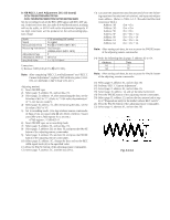
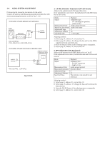
3-6. AUDIO SYSTEM ADJUSTMENT [Connecting the measuring instruments for the audio] Connect the audio system measuring instruments besides the video system measuring instruments as shown Fig. 5-3-25. • Connection of Audio generator and attenuator. Audio generator Attenuator 600 Ω AUDIO terminal Parts cord 600 Ω : 270 (1-249-410-11) + 330 (1-249-411-11) • Connection of Audio level meter or distortion meter Audio level meter or distortion meter AUDIO terminal Parts cord 47kΩ : 1-249-437-11 47kΩ Fig. 5-3-21. 1. 1.5 MHz Deviation Adjustment (VC-215 board) Adjust to the optimum audio FM signal distortion. If the adjustment is not correct, its playback level will differ from that of other units. Mode Signal Measurement Point Measuring Instrument Adjustment Page Adjustment Address Specified Value Playback Alignment tape: For checking the operation (WR5-5CSP) Audio output terminal Audio level meter F 46 -7.5±0.5dBs Adjusting method : 1) Select page: 0, address: 01, and set data: 01. 2) Select page: F, address: 46, change the data and set the 400Hz signal level to the specified value. 3) Press the PAUSE button of the adjusting remote commander. 4) Select page: 0, address: 01, and set data: 00. 2. BPF Adjustment (VC-215 board) Adjust to the optimum audio BPF characteristics of the IC. If the adjustment is not correct, the distortion rate and S/N ratio will worsen. Mode Signal Measurement Point Measuring Instrument Adjustment Page Adjustment Address Specified Value Playback Alignment tape: For BPF adjustment (WR5-11CS) Audio output terminal distortion meter F 47 The distortion rate should be and minimum. Adjusting method : 1) Select page: 0, address: 01, and set data: 01. 2) Select page: F, address: 47, change the data and minimize the distortion rate. 3) Press the PAUSE button of the adjusting remote commander. 4) Select page: 0, address: 01, and set data: 00.
-
 1
1 -
2
-
3
-
4
-
5
-
6
-
7
-
8
-
9
-
10
-
11
-
12
-
13
-
14
-
15
-
16
-
17
-
18
-
19
-
20
-
21
-
22
-
23
-
24
-
25
-
26
-
27
-
28
-
29
-
30
-
31
-
32
-
33
-
34
-
35
-
36
-
37
-
38
-
39
-
40
-
41
-
42
-
43
-
44
-
45
-
46
-
47
-
48
-
49
-
50
-
51
-
52
-
53
-
54
-
55
-
56
-
57
-
58
-
59
-
60
-
61
-
62
-
63
-
64
-
65
-
66
-
67
-
68
-
69
-
70
-
71
-
72
-
73
-
74
-
75
-
76
-
77
-
78
-
79
-
80
-
81
-
82
-
83
-
84
-
85
-
86
-
87
-
88
-
89
-
90
-
91
-
92
-
93
-
94
-
95
-
96
-
97
-
98
-
99
-
100
-
101
-
102
-
103
-
104
-
105
-
106
-
107
-
108
-
109
-
110
-
111
-
112
-
113
-
114
-
115
-
116
-
117
-
118
-
119
-
120
-
121
-
122
-
123
-
124
-
125
-
126
-
127
-
128
-
129
-
130
-
131
-
132
-
133
-
 134
134 -
 135
135 -
 136
136 -
 137
137 -
 138
138 -
 139
139 -
 140
140 -
 141
141 -
 142
142 -
 143
143 -
 144
144 -
145
-
146
-
147
-
148
-
149
-
150
-
151
-
152
-
153
-
154
-
155
-
156
-
157
-
158
-
159
-
160
-
161
-
162
-
163
-
164
-
165
-
166
-
167
-
168
-
169
-
170
-
171
-
172
-
173
-
174
-
175
-
176
-
177
 |
 |
