Sony CCD TRV16 Service Manual - Page 117
Precautions on Adjusting, Note 1, Note 2, Note 3, 1-3. Adjusting Connectors
 |
UPC - 027242551497
View all Sony CCD TRV16 manuals
Add to My Manuals
Save this manual to your list of manuals |
Page 117 highlights
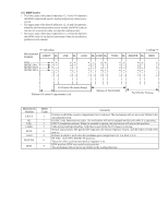
3-1-2. Precautions on Adjusting 1) The adjustments of this unit are performed in the VTR mode or camera mode. To set to the VTR mode, set the power switch to "VTR" or set the "Forced VTR Power ON mode" using the adjusting remote commander (Note 1). To set to the Camera mode, set the power switch to "CAMERA" or set the "Forced Camera Power ON mode" using the adjusting remote commander (Note 2). After completing adjustments, be sure to exit the "Forced VTR Power ON Mode" or "Forced Camera Power ON Mode". (Note 3) 2) By setting the "Forced VTR Power ON mode" or "Forced Camera Power ON mode", the video section can be operate even if even if the front panel block (MA-345/346 board, power switch, microphone unit) has been removed. When removing the front panel block disconnect the following connector. 1. VC-215 board CN916 (18P 0.5mm) 3) The lens block (CD-210/211 board) need not be connected ex- cept during battery end adjustment. To remove, disconnect the following connectors. 1. VC-215 board CN501 (16P, 0.5mm) 2. VC-215 board CN551 (23P, 0.5mm) 4) The video light model need not be assembled.If removing it. disconnect the following connect. 1. VC-215 board CN909 (4P 0.8mm) 5) Cabinet (R) ( Camera function switch (CF-60/61board), LCD block, viewfinder) need not be connected. But removing the cabinet (R) (removing the VC-215 board CN911) means removing the lithium 3V power supply (CF-60/61 board) , data such as date, time, user-set menus will be lost. After completing adjustments, reset these data. If the cabinet (R) has been removed, the self-diagnosis data, data on history of use (total drum rotation time etc. ) will be lost. Before removing, note down the selfdiagnosis data and data on the history use. (Refer to the "Service Mode" for the data on the history use.) To remove the cabinet (R), disconnect the following connectors. 1. VC-215 board CN911 (45P, 0.5mm) 2. DD-117 board CN933 (10P, 1.0mm) Note 1: Setting the "Forced VTR Power ON" mode (VTR mode) 1) Select page: 0, address: 01, and set data: 01. 2) Select page: D, address: 10, set data: 02, and press the PAUSE button of the adjusting remote commander. The above procedure will enable the VTR power to be turned on with the front panel block removed. After completing adjustments, be sure to exit the "Forced VTR Power ON mode". Note 2: Setting the "Forced Camera Power ON" mode (Camera mode) 1) Select page: 0, address: 01, and set data: 01. 2) Select page: D, address: 10, set data: 01, and press the PAUSE button of the adjusting remote commander. The above procedure will enable the camera power to be turned on with the front panel block removed. After completing adjustments, be sure to exit the "Forced Camera Power ON mode". Note 3: Exiting the "Forced Power ON" mode 1) Select page: 0, address: 01, and set data: 01. 2) Select page: D, address: 10, set data: 00, and press the PAUSE button of the adjusting remote commander. 3) Select page: 0, address: 01, and set data: 00. 3-1-3. Adjusting Connectors Some of the adjusting points of the video section are concentrated at VC-215 board CN910. Connect the measuring instruments via the CPC-7 jig (J-6082-382-A). The following table lists the pin numbers and signal names of CN910. Pin No. Signal Name 1 LANC SIG 2 XCPC IN 3 IR VIDEO 4 AFC F0 5 BPF MONI 6 PB RF 7 RF AGC IN 8 REG GND Pin No. Signal Name 9 RF AGC OUT 10 REC RF 11 RF SWP 12 CAP FG 13 EVF BL 14 EVF BL 4.75V 15 VCO 16 EVF VG Table 5-3-1. Screw driver (-) Cover Fig. 5-3-1.
-
 1
1 -
2
-
3
-
4
-
5
-
6
-
7
-
8
-
9
-
10
-
11
-
12
-
13
-
14
-
15
-
16
-
17
-
18
-
19
-
20
-
21
-
22
-
23
-
24
-
25
-
26
-
27
-
28
-
29
-
30
-
31
-
32
-
33
-
34
-
35
-
36
-
37
-
38
-
39
-
40
-
41
-
42
-
43
-
44
-
45
-
46
-
47
-
48
-
49
-
50
-
51
-
52
-
53
-
54
-
55
-
56
-
57
-
58
-
59
-
60
-
61
-
62
-
63
-
64
-
65
-
66
-
67
-
68
-
69
-
70
-
71
-
72
-
73
-
74
-
75
-
76
-
77
-
78
-
79
-
80
-
81
-
82
-
83
-
84
-
85
-
86
-
87
-
88
-
89
-
90
-
91
-
92
-
93
-
94
-
95
-
96
-
97
-
98
-
99
-
100
-
101
-
102
-
103
-
104
-
105
-
106
-
107
-
108
-
109
-
110
-
111
-
 112
112 -
 113
113 -
 114
114 -
 115
115 -
 116
116 -
 117
117 -
 118
118 -
 119
119 -
 120
120 -
 121
121 -
 122
122 -
123
-
124
-
125
-
126
-
127
-
128
-
129
-
130
-
131
-
132
-
133
-
134
-
135
-
136
-
137
-
138
-
139
-
140
-
141
-
142
-
143
-
144
-
145
-
146
-
147
-
148
-
149
-
150
-
151
-
152
-
153
-
154
-
155
-
156
-
157
-
158
-
159
-
160
-
161
-
162
-
163
-
164
-
165
-
166
-
167
-
168
-
169
-
170
-
171
-
172
-
173
-
174
-
175
-
176
-
177
 |
 |
