Sony CCD TRV16 Service Manual - Page 5
Service Note - repair
 |
UPC - 027242551497
View all Sony CCD TRV16 manuals
Add to My Manuals
Save this manual to your list of manuals |
Page 5 highlights
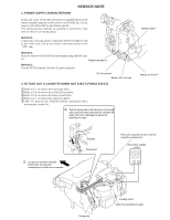
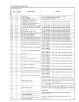
1. POWER SUPPLY DURING REPAIRS SERVICE NOTE In this unit, about 10 seconds after power is supplied (8.4V) to the battery terminal using the service power cord (J-6082-223-A), the power is shut off so that the unit cannot operate. This following three methods are available to prevent this. Take note of which to use during repairs. Method 1. Connect the servicing remote commander RM-95 (J-6082-053-B) to the LANC jack, and set the remote commander switch to the "ADJ" side. Method 2. Press the battery switch of the battery terminal using adhesive tape, etc. Battery terminal ' Method 3. Use the DC IN terminal. (Use the AC power adaptor.) DC IN terminal Battery SIG terminal 2. TO TAKE OUT A CASSETTE WHEN NOT EJECT (FORCE EJECT) 1 Refer to 2-1. to remove the front panel block. 2 Refer to 2-4. to remove the cabinet (R) assembly. 3 Refer to 2-6. to remove the battery panel block. 4 Refer to 2-7. to remove the cabinet (L) block. 5 Add +5V from the DC POWER SUPPLY and unload with a pressing the cassette lid. 6 Pull the timing belt in the direction of arrow A with a pinsette while pressing the cassette lid (take care not to damage) to adjust the bending of a tape. Battery switch Battery terminal ' A 7 Let go your hold the cassette lid and rise the cassette compartment to take out a cassette. Pinsette Timing belt Press the cassette lid not to rise the cassette compartment [DC power supply] (+5V) + - Timing belt Loading motor Adjust the bending of a tape
-
 1
1 -
 2
2 -
 3
3 -
 4
4 -
 5
5 -
 6
6 -
 7
7 -
 8
8 -
 9
9 -
 10
10 -
 11
11 -
12
-
13
-
14
-
15
-
16
-
17
-
18
-
19
-
20
-
21
-
22
-
23
-
24
-
25
-
26
-
27
-
28
-
29
-
30
-
31
-
32
-
33
-
34
-
35
-
36
-
37
-
38
-
39
-
40
-
41
-
42
-
43
-
44
-
45
-
46
-
47
-
48
-
49
-
50
-
51
-
52
-
53
-
54
-
55
-
56
-
57
-
58
-
59
-
60
-
61
-
62
-
63
-
64
-
65
-
66
-
67
-
68
-
69
-
70
-
71
-
72
-
73
-
74
-
75
-
76
-
77
-
78
-
79
-
80
-
81
-
82
-
83
-
84
-
85
-
86
-
87
-
88
-
89
-
90
-
91
-
92
-
93
-
94
-
95
-
96
-
97
-
98
-
99
-
100
-
101
-
102
-
103
-
104
-
105
-
106
-
107
-
108
-
109
-
110
-
111
-
112
-
113
-
114
-
115
-
116
-
117
-
118
-
119
-
120
-
121
-
122
-
123
-
124
-
125
-
126
-
127
-
128
-
129
-
130
-
131
-
132
-
133
-
134
-
135
-
136
-
137
-
138
-
139
-
140
-
141
-
142
-
143
-
144
-
145
-
146
-
147
-
148
-
149
-
150
-
151
-
152
-
153
-
154
-
155
-
156
-
157
-
158
-
159
-
160
-
161
-
162
-
163
-
164
-
165
-
166
-
167
-
168
-
169
-
170
-
171
-
172
-
173
-
174
-
175
-
176
-
177
 |
 |
