Sony CCD TRV16 Service Manual - Page 8

Service Note, Self-diagnosis Function, General, Table Of Contents, Disassembly, Block Diagrams - parts

Page 8 highlights

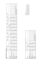
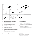
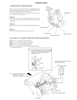
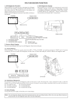
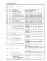
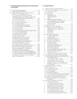
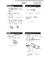
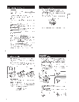
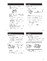
TABLE OF CONTENTS SERVICE NOTE 2. DISASSEMBLY 1. Power Supply During Repairs 5 2. To Take out a Cassette when not Eject (Force Eject 5 Self-Diagnosis Function 1. Self-diagnosis function 6 2. Self-diagnosis Display 6 3. Service Mode Display 6 3-1. Display Method 6 3-2. Switching of Backup No 6 3-3. End of Display 6 4. Self-diagnosis Code Table 7 1. GENERAL This section is extacked from instruction manual of CCD-TRV36/TRV43/TRV46. Using this manual 1-1 Checking supplied accessories 1-1 Installing and Charging the battery pack 1-1 Inserting a cassette 1-2 Camera recording 1-2 Hints for better Shooting 1-4 Checking the recorded picture 1-4 Playing back a tape 1-5 Searching for the end of the picture 1-5 Using alternative power sources 1-6 Changing the mode settings 1-6 Shooting with backlighting 1-7 Using the FADER function 1-7 Shooting in the dark (NightShot 1-8 Using the wide mode function 1-8 Using the PROGRAM AE function 1-9 Focusing manually 1-9 Enjoying picture effect 1-10 Adjusting the exposure 1-10 Superimposing a title 1-11 Making your own titles 1-11 Recording with the date/time 1-11 Optimizing the recording condition 1-12 Using the built-in light 1-12 Releasing the STEADYSHOT function 1-12 Watching on a TV screen 1-13 Editing onto another tape 1-13 Changing the lithium battery in the camcoder 1-13 Resetting the date and time 1-14 Simple setting of clock by time difference 1-14 Usable cassettes and playback modes 1-14 Tips for using the battery pack 1-15 Maintenance information and precautions 1-15 Using your camcorder abroad 1-17 Truoble check 1-17 Self-diagnosis display 1-18 Identifying the parts 1-18 Warning Indicators 1-20 2-1. Removal of Front Panel Block and Video Light Block .... 2-1 2-2. Removal of LB-54, VF-119 and VF-120 Boards (Color View Finder Models 2-2 2-3. Removal of VF-99 Board and CRT Assembly (B/W View Finder Models 2-2 2-4. Removal of Cabinet (R) Block 2-3 2-5. Removal of Cassette Lid Assembly 2-3 2-6. Removal of Battery Panel Block 2-3 2-7. Removal of Cabinet (L) Block 2-4 2-8. Removal of Control Switch Block (FK-8500 2-4 2-9. Removal of Zoom Lens Block and VL-20/21 Board ....... 2-4 2-10. Removal of DD-117 and PJ-90/91 Boards 2-4 2-11. Removal of VC-215 abd SE-80/81 Boards 2-5 2-12. Removal of View Finder Block 2-5 2-13. Removal of TR Cover, CF-60 Board and Display Panel (TR series 2-6 2-14. Removal of IR Cover, CF-61 Board and LCD Panel (TRV series 2-6 2-15. Service Position 2-7 2-16. Circuit Boards Location 2-8 2-17. Flexible Boards and Flat Cables Location 2-8 3. BLOCK DIAGRAMS 3-1. Overall Block Diagram 3-1 3-2. Camera/Video 1 Block Diagram 3-5 3-3. VTR/Camera Control Block Diagram 3-9 3-4. Servo Block Diagram 3-12 3-5. Mode Control Block Diagram 3-15 3-6. Audio Block Diagram 3-19 3-7. LCD Block Diagram (TRV model 3-23 3-8. Color EVF Block Diagram (Color EVF model 3-26 3-9. B/W EVF Block Diagram (B/W EVF model 3-29 3-10. Power Block Diagram 3-33

  • 1
  • 2
  • 3
  • 4
  • 5
  • 6
  • 7
  • 8
  • 9
  • 10
  • 11
  • 12
  • 13
  • 14
  • 15
  • 16
  • 17
  • 18
  • 19
  • 20
  • 21
  • 22
  • 23
  • 24
  • 25
  • 26
  • 27
  • 28
  • 29
  • 30
  • 31
  • 32
  • 33
  • 34
  • 35
  • 36
  • 37
  • 38
  • 39
  • 40
  • 41
  • 42
  • 43
  • 44
  • 45
  • 46
  • 47
  • 48
  • 49
  • 50
  • 51
  • 52
  • 53
  • 54
  • 55
  • 56
  • 57
  • 58
  • 59
  • 60
  • 61
  • 62
  • 63
  • 64
  • 65
  • 66
  • 67
  • 68
  • 69
  • 70
  • 71
  • 72
  • 73
  • 74
  • 75
  • 76
  • 77
  • 78
  • 79
  • 80
  • 81
  • 82
  • 83
  • 84
  • 85
  • 86
  • 87
  • 88
  • 89
  • 90
  • 91
  • 92
  • 93
  • 94
  • 95
  • 96
  • 97
  • 98
  • 99
  • 100
  • 101
  • 102
  • 103
  • 104
  • 105
  • 106
  • 107
  • 108
  • 109
  • 110
  • 111
  • 112
  • 113
  • 114
  • 115
  • 116
  • 117
  • 118
  • 119
  • 120
  • 121
  • 122
  • 123
  • 124
  • 125
  • 126
  • 127
  • 128
  • 129
  • 130
  • 131
  • 132
  • 133
  • 134
  • 135
  • 136
  • 137
  • 138
  • 139
  • 140
  • 141
  • 142
  • 143
  • 144
  • 145
  • 146
  • 147
  • 148
  • 149
  • 150
  • 151
  • 152
  • 153
  • 154
  • 155
  • 156
  • 157
  • 158
  • 159
  • 160
  • 161
  • 162
  • 163
  • 164
  • 165
  • 166
  • 167
  • 168
  • 169
  • 170
  • 171
  • 172
  • 173
  • 174
  • 175
  • 176
  • 177

– 8 –
SERVICE NOTE
1.
Power Supply During Repairs
................................................
5
2.
To Take out a Cassette when not Eject (Force Eject)
..............
5
Self-Diagnosis Function
1.
Self-diagnosis function
............................................................
6
2.
Self-diagnosis Display
.............................................................
6
3.
Service Mode Display
.............................................................
6
3-1. Display Method
................................................................
6
3-2. Switching of Backup No
. .................................................
6
3-3. End of Display
.................................................................
6
4.
Self-diagnosis Code Table
.......................................................
7
1. GENERAL
This section is extacked from instruction manual of
CCD-TRV36/TRV43/TRV46.
Using this manual
......................................................................
1-1
Checking supplied accessories
..................................................
1-1
Installing and Charging the battery pack
...................................
1-1
Inserting a cassette
.....................................................................
1-2
Camera recording
......................................................................
1-2
Hints for better Shooting
...........................................................
1-4
Checking the recorded picture
...................................................
1-4
Playing back a tape
....................................................................
1-5
Searching for the end of the picture
..........................................
1-5
Using alternative power sources
................................................
1-6
Changing the mode settings
......................................................
1-6
Shooting with backlighting
.......................................................
1-7
Using the FADER function
.......................................................
1-7
Shooting in the dark (NightShot)
..............................................
1-8
Using the wide mode function
...................................................
1-8
Using the PROGRAM AE function
...........................................
1-9
Focusing manually
.....................................................................
1-9
Enjoying picture effect
............................................................
1-10
Adjusting the exposure
............................................................
1-10
Superimposing a title
...............................................................
1-11
Making your own titles
............................................................
1-11
Recording with the date/time
...................................................
1-11
Optimizing the recording condition
.........................................
1-12
Using the built-in light
.............................................................
1-12
Releasing the STEADYSHOT function
..................................
1-12
Watching on a TV screen
.........................................................
1-13
Editing onto another tape
.........................................................
1-13
Changing the lithium battery in the camcoder
........................
1-13
Resetting the date and time
......................................................
1-14
Simple setting of clock by time difference
..............................
1-14
Usable cassettes and playback modes
.....................................
1-14
Tips for using the battery pack
................................................
1-15
Maintenance information and precautions
..............................
1-15
Using your camcorder abroad
.................................................
1-17
Truoble check
..........................................................................
1-17
Self-diagnosis display
..............................................................
1-18
Identifying the parts
.................................................................
1-18
Warning Indicators
..................................................................
1-20
TABLE OF CONTENTS
2. DISASSEMBLY
2-1.
Removal of Front Panel Block and Video Light Block
....
2-1
2-2.
Removal of LB-54, VF-119 and
VF-120 Boards (Color View Finder Models)
..................
2-2
2-3.
Removal of VF-99 Board and
CRT Assembly (B/W View Finder Models)
.....................
2-2
2-4.
Removal of Cabinet (R) Block
.........................................
2-3
2-5.
Removal of Cassette Lid Assembly
.................................
2-3
2-6.
Removal of Battery Panel Block
..........................................
2-3
2-7.
Removal of Cabinet (L) Block
.........................................
2-4
2-8.
Removal of Control Switch Block (FK-8500)
.................
2-4
2-9.
Removal of Zoom Lens Block and VL-20/21 Board
.......
2-4
2-10. Removal of DD-117 and PJ-90/91 Boards
.......................
2-4
2-11. Removal of VC-215 abd SE-80/81 Boards
......................
2-5
2-12. Removal of View Finder Block
........................................
2-5
2-13. Removal of TR Cover, CF-60 Board and
Display Panel (TR series)
................................................
2-6
2-14. Removal of IR Cover, CF-61 Board
and LCD Panel (TRV series)
............................................
2-6
2-15. Service Position
...............................................................
2-7
2-16. Circuit Boards Location
...................................................
2-8
2-17. Flexible Boards and Flat Cables Location
.......................
2-8
3.
BLOCK DIAGRAMS
3-1.
Overall Block Diagram
....................................................
3-1
3-2.
Camera/Video 1 Block Diagram
......................................
3-5
3-3.
VTR/Camera Control Block Diagram
.............................
3-9
3-4.
Servo Block Diagram
.....................................................
3-12
3-5.
Mode Control Block Diagram
........................................
3-15
3-6.
Audio Block Diagram
....................................................
3-19
3-7.
LCD Block Diagram (TRV model)
....................................
3-23
3-8.
Color EVF Block Diagram (Color EVF model)
............
3-26
3-9.
B/W EVF Block Diagram (B/W EVF model)
...............
3-29
3-10. Power Block Diagram
....................................................
3-33