Sony CCD TRV16 Service Manual - Page 128
VIDEO SYSTEM ADJUSTMENTS, 28 MHz Origin Oscillation Adjustment VC-215 board
 |
UPC - 027242551497
View all Sony CCD TRV16 manuals
Add to My Manuals
Save this manual to your list of manuals |
Page 128 highlights
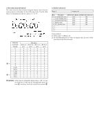
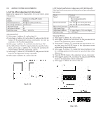
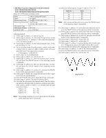
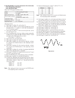
3-4. VIDEO SYSTEM ADJUSTMENTS Video system adjustments must be performed in the following order. [Adjusting Order] 1. 28MHz origin oscillation adjustment 2. AFC f0 adjustment 3. Filter f0 adjustment 4. Y OUT level adjustment 5. C OUT level adjustment 6. RP filter f0 adjustment 7. Hi8 REC Y current adjustment 8. Standard REC Y current adjustment 9. Hi8 REC L level adjustment 10. Standard8 REC L level adjustment 11. REC C current adjustment 1. 28 MHz Origin Oscillation Adjustment (VC-215 board) Set the frequency of the clock for synchronization. If deviated, the synchronization will be disrupted and the color will become inconsistent. Mode Signal Measurement Point Measuring Instrument Adjustment Page Adjustment Address Specified Value VTR stop No signal Pin ^§ of IC202 or pin !™ of IC501 Frequency counter F 2C Pin ^§ of IC202 : f=3579545±17Hz Pin !™ of IC501 : f=14318181±68Hz Adjusting method: 1) Select page: 0, address: 01, and set data: 01. 2) Select page: 2, address: 61, and set data: 30. 3) Select page: 3, address: 01, set data: 41, and press the PAUSE button of the adjusting remote commander. 4) Select page: F, address: 2C, change the data and set the clock frequency(f) to the specified value. 5) Press the PAUSE button of the adjusting remote commander. 6) Select page: 2, address: 61, and set data: 10. 7) Select page: 3, address: 01, set data: 00, and press the PAUSE button of the adjusting remote commander. 6) Select page: 0, address: 01, and set data: 00.
-
 1
1 -
2
-
3
-
4
-
5
-
6
-
7
-
8
-
9
-
10
-
11
-
12
-
13
-
14
-
15
-
16
-
17
-
18
-
19
-
20
-
21
-
22
-
23
-
24
-
25
-
26
-
27
-
28
-
29
-
30
-
31
-
32
-
33
-
34
-
35
-
36
-
37
-
38
-
39
-
40
-
41
-
42
-
43
-
44
-
45
-
46
-
47
-
48
-
49
-
50
-
51
-
52
-
53
-
54
-
55
-
56
-
57
-
58
-
59
-
60
-
61
-
62
-
63
-
64
-
65
-
66
-
67
-
68
-
69
-
70
-
71
-
72
-
73
-
74
-
75
-
76
-
77
-
78
-
79
-
80
-
81
-
82
-
83
-
84
-
85
-
86
-
87
-
88
-
89
-
90
-
91
-
92
-
93
-
94
-
95
-
96
-
97
-
98
-
99
-
100
-
101
-
102
-
103
-
104
-
105
-
106
-
107
-
108
-
109
-
110
-
111
-
112
-
113
-
114
-
115
-
116
-
117
-
118
-
119
-
120
-
121
-
122
-
 123
123 -
 124
124 -
 125
125 -
 126
126 -
 127
127 -
 128
128 -
 129
129 -
 130
130 -
 131
131 -
 132
132 -
 133
133 -
134
-
135
-
136
-
137
-
138
-
139
-
140
-
141
-
142
-
143
-
144
-
145
-
146
-
147
-
148
-
149
-
150
-
151
-
152
-
153
-
154
-
155
-
156
-
157
-
158
-
159
-
160
-
161
-
162
-
163
-
164
-
165
-
166
-
167
-
168
-
169
-
170
-
171
-
172
-
173
-
174
-
175
-
176
-
177
 |
 |
