Sony CCD TRV16 Service Manual - Page 104
Color Electronic Viewfinder System, Adjustment
 |
UPC - 027242551497
View all Sony CCD TRV16 manuals
Add to My Manuals
Save this manual to your list of manuals |
Page 104 highlights
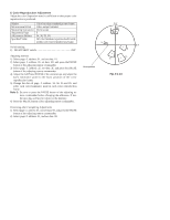
1-4. COLOR ELECTRONIC VIEWFINDER SYSTEM ADJUSTMENT (CCD-TR416/TR416PK/TR516/TR516PK/TR716) Note 1: The back light (fluorescent tube) is driven by a high voltage AC power supply. Therefore, do not touch the back light holder to avoid electrical shock. Note 2: When replacing the LCD unit, be careful to prevent damages caused by static electricity. [Adjusting connector] Most of the measuring points for adjusting the viewfinder system are concentrated in CN910 of the VC-215 board. Connect the measuring instruments via the CPC-7 jig (J-6082-382A). The following table shows the Pin No. and signal name of CN910. Pin No. Signal Name 1 LANC SIG 2 XCPC IN 3 IR VIDEO 4 AFC F0 5 BPF MONI 6 PB RF 7 RF AGC IN 8 REG GND Pin No. Signal Name 9 RF AGC OUT 10 REC RF 11 RF SWP 12 CAP FG 13 EVF BL 14 EVF BL 4.75V 15 VCO 16 EVF VG 1. EVF Initial Data Input Mode Signal Adjustment Page Adjusting Address VTR stop No signal E C2 to CD Adjusting method: 1) Select page: 0, address: 01, and set data: 01. 2) Select page: E, and input the data in the following table. Note: To write in the non-volatile memory (EEPROM), press the PAUSE button of the adjusting remote commander each time to set the data. 3) Select page: 0, address: 01, and set data: 00. Address C2 C3 C4 C5 C6 C7 C8 C9 CA CB CC Data B0 80 77 80 80 68 50 F8 A8 3C B0 CD 70 Remark VCO adjustment Bright adjustment Contrast adjustment White balance adjustment White balance adjustment Fixed value Fixed value Fixed value Fixed value Fixed value Backlight Consumption Current Adjustment Fixed value Screw driver (-) Cover Fig.5-1-12
-
 1
1 -
2
-
3
-
4
-
5
-
6
-
7
-
8
-
9
-
10
-
11
-
12
-
13
-
14
-
15
-
16
-
17
-
18
-
19
-
20
-
21
-
22
-
23
-
24
-
25
-
26
-
27
-
28
-
29
-
30
-
31
-
32
-
33
-
34
-
35
-
36
-
37
-
38
-
39
-
40
-
41
-
42
-
43
-
44
-
45
-
46
-
47
-
48
-
49
-
50
-
51
-
52
-
53
-
54
-
55
-
56
-
57
-
58
-
59
-
60
-
61
-
62
-
63
-
64
-
65
-
66
-
67
-
68
-
69
-
70
-
71
-
72
-
73
-
74
-
75
-
76
-
77
-
78
-
79
-
80
-
81
-
82
-
83
-
84
-
85
-
86
-
87
-
88
-
89
-
90
-
91
-
92
-
93
-
94
-
95
-
96
-
97
-
98
-
 99
99 -
 100
100 -
 101
101 -
 102
102 -
 103
103 -
 104
104 -
 105
105 -
 106
106 -
 107
107 -
 108
108 -
 109
109 -
110
-
111
-
112
-
113
-
114
-
115
-
116
-
117
-
118
-
119
-
120
-
121
-
122
-
123
-
124
-
125
-
126
-
127
-
128
-
129
-
130
-
131
-
132
-
133
-
134
-
135
-
136
-
137
-
138
-
139
-
140
-
141
-
142
-
143
-
144
-
145
-
146
-
147
-
148
-
149
-
150
-
151
-
152
-
153
-
154
-
155
-
156
-
157
-
158
-
159
-
160
-
161
-
162
-
163
-
164
-
165
-
166
-
167
-
168
-
169
-
170
-
171
-
172
-
173
-
174
-
175
-
176
-
177
 |
 |
