Sony CCD TRV16 Service Manual - Page 87
Fig. 5-1-7., Table 5-1-1.
 |
UPC - 027242551497
View all Sony CCD TRV16 manuals
Add to My Manuals
Save this manual to your list of manuals |
Page 87 highlights
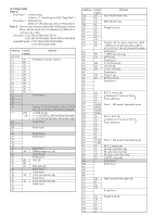
1-1-4. Adjusting Remote Commander The adjusting remote commander is used for changing the calculation coefficient in signal processing, EVR data, etc. The adjusting remote commander performs bi-directional communication with the unit using the remote commander signal line (LANC). The resultant data of this bi-directional communication is written in the nonvolatile memory. 1. Using the adjusting remote commander 1) Connect the adjusting remote commander to the LANC terminal. 2) Adjust the HOLD switch of the adjusting remote commander to "HOLD" (SERVICE position). If it has been properly connected, the LCD on the adjusting remote commander will display as shown in Fig. 5-1-7. Page Data Address • Changing the address The address increases when the FF ()) button is pressed, and decreases when the REW (0) button is pressed. There are altogether 256 addresses, from 00 to FF. • Changing the data (Data setting) The data increases when the PLAY (() button is pressed, and decreases when the STOP (p) button is pressed. There are altogether 256 data, from 00 to FF. • Writing the adjustment data The PAUSE button must be pressed to write the adjustment data (D, E, F page) in the nonvolatile memory. (The new adjustment data will not be recorded in the nonvolatile memory if this step is not performed.) 4) Select page: 0, address: 01, and set the data to 01, and enables Page D and E, F to be adjusted. 5) After completing all adjustments, set data: 00 to page: 0, address: 01 and turn off the main power supply (8.4V) once. 2. Precautions upon using the adjusting remote commander Mishandling of the adjusting remote commander may erase the correct adjustment data at times. To prevent this, it is recommended that all adjustment data be noted down before beginning adjustments and new adjustment data after each adjustment. Fig. 5-1-7. 3) Operate the adjusting remote commander as follows. • Changing the page The page increases when the EDIT SEARCH+ button is pressed, and decreases when the EDIT SEARCH- button is pressed. There are altogether 16 pages, from 0 to F. Hexadecimal notation 0123456 789ABCDE F LCD Display 0 1 2 3 4 5 6 7 8 9 A b c d E F Decimal notation conversion value 0 1 2 3 4 5 6 7 8 9 10 11 12 13 14 15 Table 5-1-1.
-
 1
1 -
2
-
3
-
4
-
5
-
6
-
7
-
8
-
9
-
10
-
11
-
12
-
13
-
14
-
15
-
16
-
17
-
18
-
19
-
20
-
21
-
22
-
23
-
24
-
25
-
26
-
27
-
28
-
29
-
30
-
31
-
32
-
33
-
34
-
35
-
36
-
37
-
38
-
39
-
40
-
41
-
42
-
43
-
44
-
45
-
46
-
47
-
48
-
49
-
50
-
51
-
52
-
53
-
54
-
55
-
56
-
57
-
58
-
59
-
60
-
61
-
62
-
63
-
64
-
65
-
66
-
67
-
68
-
69
-
70
-
71
-
72
-
73
-
74
-
75
-
76
-
77
-
78
-
79
-
80
-
81
-
 82
82 -
 83
83 -
 84
84 -
 85
85 -
 86
86 -
 87
87 -
 88
88 -
 89
89 -
 90
90 -
 91
91 -
 92
92 -
93
-
94
-
95
-
96
-
97
-
98
-
99
-
100
-
101
-
102
-
103
-
104
-
105
-
106
-
107
-
108
-
109
-
110
-
111
-
112
-
113
-
114
-
115
-
116
-
117
-
118
-
119
-
120
-
121
-
122
-
123
-
124
-
125
-
126
-
127
-
128
-
129
-
130
-
131
-
132
-
133
-
134
-
135
-
136
-
137
-
138
-
139
-
140
-
141
-
142
-
143
-
144
-
145
-
146
-
147
-
148
-
149
-
150
-
151
-
152
-
153
-
154
-
155
-
156
-
157
-
158
-
159
-
160
-
161
-
162
-
163
-
164
-
165
-
166
-
167
-
168
-
169
-
170
-
171
-
172
-
173
-
174
-
175
-
176
-
177
 |
 |
