Sony CCD TRV16 Service Manual - Page 6
Self-diagnosis Function - problems
 |
UPC - 027242551497
View all Sony CCD TRV16 manuals
Add to My Manuals
Save this manual to your list of manuals |
Page 6 highlights
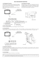
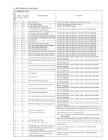
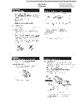
SELF-DIAGNOSIS FUNCTION 1. Self-diagnosis Function When problems occur while the unit is operating, the self-diagnosis function starts working, and displays on the viewfinder or Dis- play window what to do. This function consists of two display; selfdiagnosis display and service mode display. Details of the self-diagnosis functions are provided in the Instruc- tion manual. Viewfinder Display window 2. Self-diagnosis display When problems occur while the unit is operating, the counter of the viewfinder or Display window shows a 4-digit display consisting of an alphabet and numbers, which blinks at 3.2 Hz. This 5-character display indicates the "repaired by:", "block" in which the problem occurred, and "detailed code" of the problem. C : 3 1 : 1 1 C : 3 1 : 1 1 Blinks at 3.2 Hz C 31 11 Display window Repairede by : Block Detailed Code Refer to page7 Self-diagnosis Code table C : Corrected by customer Indicates the appropriate step to be taken H : Corrected by dealer E. g. E : Corrected by service engineer 31 ... Reload the tape. 32 ... Turn on power again. 3. Service Mode Display The service mode display shows up to six self-diagnosis codes shown in the past. 3-1. Display Method While pressing the "STOP" key, set the switch from OFF to "VTR or PLAYER", and continue pressing the "STOP" key for 5 seconds continuously. The service mode will be displayed, and the counter will show the backup No. and the 5-character self-diagnosis codes. Viewfinder [3] C : 3 1 : 1 1 Display window 3 C : 3 1 : 1 1 Lights up [3] C : 3 1 : 1 1 Backup No. Self-diagnosis codes Order of previous errors Control dial 3-2. Switching of Backup No. By rotating the control dial, past self-diagnosis codes will be shown in order. The backup No. in the [] indicates the order in which the problem occurred. (If the number of problems which occurred is less than 6, only the number of problems which occurred will be shown.) [1] : Occurred first time [4] : Occurred fourth time [2] : Occurred second time [5] : Occurred fifth time [3] : Occurred third time [6] : Occurred the last time 3-3. End of Display Turning OFF the power supply will end the service mode display. Note: The self-diagnosis display data will be backed up by the coin-type lithium battery. When this coin-type lithium battery is disconnected, the self-diagnosis data will be lost by initialization.
-
 1
1 -
 2
2 -
 3
3 -
 4
4 -
 5
5 -
 6
6 -
 7
7 -
 8
8 -
 9
9 -
 10
10 -
 11
11 -
 12
12 -
13
-
14
-
15
-
16
-
17
-
18
-
19
-
20
-
21
-
22
-
23
-
24
-
25
-
26
-
27
-
28
-
29
-
30
-
31
-
32
-
33
-
34
-
35
-
36
-
37
-
38
-
39
-
40
-
41
-
42
-
43
-
44
-
45
-
46
-
47
-
48
-
49
-
50
-
51
-
52
-
53
-
54
-
55
-
56
-
57
-
58
-
59
-
60
-
61
-
62
-
63
-
64
-
65
-
66
-
67
-
68
-
69
-
70
-
71
-
72
-
73
-
74
-
75
-
76
-
77
-
78
-
79
-
80
-
81
-
82
-
83
-
84
-
85
-
86
-
87
-
88
-
89
-
90
-
91
-
92
-
93
-
94
-
95
-
96
-
97
-
98
-
99
-
100
-
101
-
102
-
103
-
104
-
105
-
106
-
107
-
108
-
109
-
110
-
111
-
112
-
113
-
114
-
115
-
116
-
117
-
118
-
119
-
120
-
121
-
122
-
123
-
124
-
125
-
126
-
127
-
128
-
129
-
130
-
131
-
132
-
133
-
134
-
135
-
136
-
137
-
138
-
139
-
140
-
141
-
142
-
143
-
144
-
145
-
146
-
147
-
148
-
149
-
150
-
151
-
152
-
153
-
154
-
155
-
156
-
157
-
158
-
159
-
160
-
161
-
162
-
163
-
164
-
165
-
166
-
167
-
168
-
169
-
170
-
171
-
172
-
173
-
174
-
175
-
176
-
177
 |
 |
