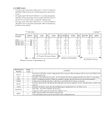
Sony CCD TRV16 Service Manual - Page 122
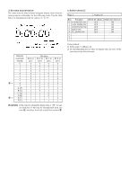
MSW Codes
 |
UPC - 027242551497
View all Sony CCD TRV16 manuals
Add to My Manuals
Save this manual to your list of manuals |
Page 122 highlights
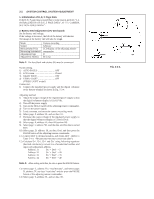
2-2. MSW Codes • The lower parts of the data of addresses 12, 16 and 1A represent the MSW codes (mode switch, mechanism position) when errors occurs. • The upper parts of the data of addresses 12, 16 and 1A represent, when the mechanism position is to be moved, the MSW codes at the start of movement (when moving the loading motor). • The lower parts of the data of addresses 13, 17 and 1B represent the MSW codes of the desired movement when the mechanism position is to be moved. N Unloading Mechanism Position EJECT BL MSB ( MODE SW C ( MODE SW B ( MODE SW A ( USE Loading n BL LOAD BL STOP BL TURN BL REC/PB BL REW 0 1 0 1 = 5 0 1 1 1 = 7 0 0 0 0 = 0 0 1 1 1 = 7 0 1 0 0 = 4 0 1 1 1 = 7 0 1 1 0 = 6 0 1 1 1 = 7 0 0 1 0 = 2 0 1 1 1 = 7 0 0 1 1 = 3 0 1 1 1 = 7 0 0 0 1 = 1 LS Chassis Movement Range 9 ( Release of Cassette Compartment Lock 9 Release of Pinch Roller ( 9 ( Pinch Roller Pressing Mechanism Position EJECT BL USE LOAD STOP TURN RECP/PB REW MSW Code 1 7 3 2 6 4 0 5 Contents Position at which the cassette compartment lock is released. The mechanism will not move any further in the unloading direction. BLANC code. Between two codes. The mechanism will not be stopped by this code while it is operating. EJECT completion position. When the cassette is ejected, the mechanism will stop at this position. Code during loading/unloading. Code that is used while the LS chassis is moving. Normal stop position. The pinch roller separates, the tension regulator returns, and the brakes of both reels turn on. Position at which is used when the pendulum gear swings from S to T or from T to S. PB, REC, CUE, REV, PAUSE, FF positions. The pinch roller is pressed and tension regulator is on. REW position. REW are carried at this position. The mechanism will not move any further in the loading direction.
-
 1
1 -
2
-
3
-
4
-
5
-
6
-
7
-
8
-
9
-
10
-
11
-
12
-
13
-
14
-
15
-
16
-
17
-
18
-
19
-
20
-
21
-
22
-
23
-
24
-
25
-
26
-
27
-
28
-
29
-
30
-
31
-
32
-
33
-
34
-
35
-
36
-
37
-
38
-
39
-
40
-
41
-
42
-
43
-
44
-
45
-
46
-
47
-
48
-
49
-
50
-
51
-
52
-
53
-
54
-
55
-
56
-
57
-
58
-
59
-
60
-
61
-
62
-
63
-
64
-
65
-
66
-
67
-
68
-
69
-
70
-
71
-
72
-
73
-
74
-
75
-
76
-
77
-
78
-
79
-
80
-
81
-
82
-
83
-
84
-
85
-
86
-
87
-
88
-
89
-
90
-
91
-
92
-
93
-
94
-
95
-
96
-
97
-
98
-
99
-
100
-
101
-
102
-
103
-
104
-
105
-
106
-
107
-
108
-
109
-
110
-
111
-
112
-
113
-
114
-
115
-
116
-
 117
117 -
 118
118 -
 119
119 -
 120
120 -
 121
121 -
 122
122 -
 123
123 -
 124
124 -
 125
125 -
 126
126 -
 127
127 -
128
-
129
-
130
-
131
-
132
-
133
-
134
-
135
-
136
-
137
-
138
-
139
-
140
-
141
-
142
-
143
-
144
-
145
-
146
-
147
-
148
-
149
-
150
-
151
-
152
-
153
-
154
-
155
-
156
-
157
-
158
-
159
-
160
-
161
-
162
-
163
-
164
-
165
-
166
-
167
-
168
-
169
-
170
-
171
-
172
-
173
-
174
-
175
-
176
-
177
 |
 |
