Sony CCD TRV16 Service Manual - Page 106
Contrast Adjustment VF-119 board, Backlight Consumption Current Adjustment VF-120, board, White
 |
UPC - 027242551497
View all Sony CCD TRV16 manuals
Add to My Manuals
Save this manual to your list of manuals |
Page 106 highlights
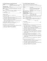
4. Contrast Adjustment (VF-119 board) Set the level of the VIDEO signal for driving the LCD to the specified value. If deviated, the screen image will be blackish or saturated (whitish). Mode Signal Measurement Point Measuring Instrument Adjustment Page Adjustment Address Specified Value VTR stop No signal Pin !§ of CN910 (EVF VG) on VC-215 board Oscilloscope E C4 A = 2.1 ± 0.1V Adjusting method: 1) Select page: 0, address: 01, and set data: 01. 2) Select page: 3, address: 01, set data: 55, and press the PAUSE button of the adjusting remote commander. 3) Select page: E, address: C4, change the data and set the voltage (A) between the 7 step peak and the pedestal to the specified value. 4) Press the PAUSE button of the adjusting remote commander. 5) Select page: 3, address: 01, set data: 00, and press the PAUSE button of the adjusting remote commander. 6) Select page: 0, address: 01, and set data: 00. 7 step peak A 2H Fig. 5-1-15. 5. Backlight Consumption Current Adjustment (VF-120 board) Set the backlight luminance and color temperature. If deviated, the image may become dark or bright. Mode Signal Measurement Point Measuring Instrument Adjustment Page Adjustment Address Specified Value VTR stop No signal + Probe: Pin !¢ of CN910 (EVF BL 4.75V) on VC-215 board - Probe: Pin !£ of CN910 (EVF BL) on VC-215 board Digital voltmeter E CC A = 21.0 ± 1.0 mVdc Note: Adjust 30 seconds after running on the power supply. Adjusting method: 1) Select page: 0, address: 01, and set data: 01. 2) Select page: 3, address: 01, set data: 55, and press the PAUSE button of the adjusting remote commander. 3) Select page: E, address: CC, change the data and set the voltage difference (A) between Pin !¢ of CN910 (EVF BL 4.75V) and Pin !£ of CN910 (EVF BL) to the specified value. 4) Press the PAUSE button of the adjusting remote commander. 5) Select page: 3, address: 01, set data: 00, and press the PAUSE button of the adjusting remote commander. 6) Select page: 0, address: 01, and set data: 00. 6. White Balance Adjustment (VF-119 board) Correct the white balance. If deviated, the reproduction of the EVF screen may degenerate. Mode Signal Measurement Point Measuring Instrument Adjustment Page Adjustment Address Specified Value VTR stop No signal Check on EVF screen E C5, C6 The EVF screen should not be colored. Adjusting method: 1) Select page: 0, address: 01, and set data: 01. 2) Select page: 3, address: 01, set data: 51, and press the PAUSE button of the adjusting remote commander. 3) Select page: 2, address: 7D, and set data: 03. 4) Select page: E, address: C5 and C6, set the data to the initial value. Note: To write in the non-volatile memory (EEPROM), press the PAUSE button of the adjusting remote commander each time to set the data. Address C5 C6 Data 80 80 5) Check that the LCD screen is not colored. If colored, change the data of page: E, address: C5 and C6 so that the EVF screen is not colored. Note: To write in the non-volatile memory (EEPROM), press the PAUSE button of the adjusting remote commander each time to set the data. 6) Select page: 2, address: 7D, and set data: 00. 7) Select page: 3, address: 01, set data: 00, and press the PAUSE button of the adjusting remote commander. 8) Select page: 0, address: 01, and set data: 00.
-
 1
1 -
2
-
3
-
4
-
5
-
6
-
7
-
8
-
9
-
10
-
11
-
12
-
13
-
14
-
15
-
16
-
17
-
18
-
19
-
20
-
21
-
22
-
23
-
24
-
25
-
26
-
27
-
28
-
29
-
30
-
31
-
32
-
33
-
34
-
35
-
36
-
37
-
38
-
39
-
40
-
41
-
42
-
43
-
44
-
45
-
46
-
47
-
48
-
49
-
50
-
51
-
52
-
53
-
54
-
55
-
56
-
57
-
58
-
59
-
60
-
61
-
62
-
63
-
64
-
65
-
66
-
67
-
68
-
69
-
70
-
71
-
72
-
73
-
74
-
75
-
76
-
77
-
78
-
79
-
80
-
81
-
82
-
83
-
84
-
85
-
86
-
87
-
88
-
89
-
90
-
91
-
92
-
93
-
94
-
95
-
96
-
97
-
98
-
99
-
100
-
 101
101 -
 102
102 -
 103
103 -
 104
104 -
 105
105 -
 106
106 -
 107
107 -
 108
108 -
 109
109 -
 110
110 -
 111
111 -
112
-
113
-
114
-
115
-
116
-
117
-
118
-
119
-
120
-
121
-
122
-
123
-
124
-
125
-
126
-
127
-
128
-
129
-
130
-
131
-
132
-
133
-
134
-
135
-
136
-
137
-
138
-
139
-
140
-
141
-
142
-
143
-
144
-
145
-
146
-
147
-
148
-
149
-
150
-
151
-
152
-
153
-
154
-
155
-
156
-
157
-
158
-
159
-
160
-
161
-
162
-
163
-
164
-
165
-
166
-
167
-
168
-
169
-
170
-
171
-
172
-
173
-
174
-
175
-
176
-
177
 |
 |
