Sony STR-DH710 Operating Instructions - Page 30
Connecting components with, analog video and audio jack
 |
UPC - 027242779976
View all Sony STR-DH710 manuals
Add to My Manuals
Save this manual to your list of manuals |
Page 30 highlights
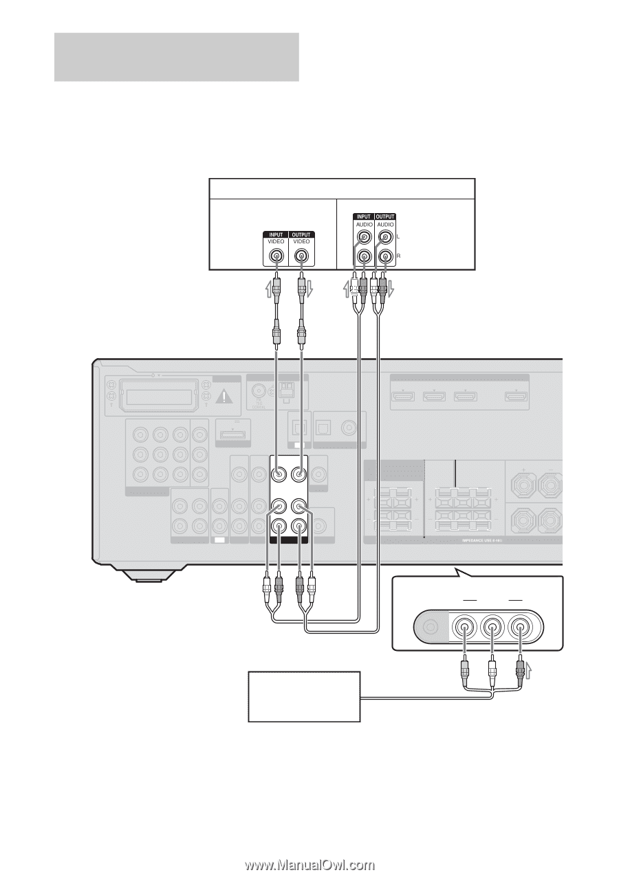
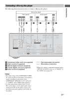
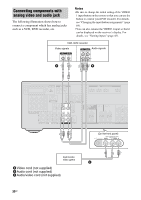
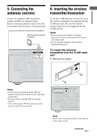
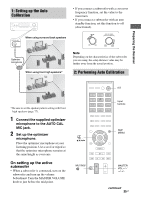
Connecting components with analog video and audio jack The following illustration shows how to connect a component which has analog jacks such as a VCR, DVD recorder, etc. Notes • Be sure to change the initial setting of the VIDEO 1 input button on the remote so that you can use the button to control your DVD recorder. For details, see "Changing the input button assignments" (page 84). • You can also rename the VIDEO 1 input so that it can be displayed on the receiver's display. For details, see "Naming inputs" (page 43). VCR, DVD recorder Video signals Audio signals A B EZW-T100 ANTENNA HDMI ASSIGNABLE (INPUT ONLY) IN 3 IN 2 IN 1 AM IN 3 IN 2 IN 1 MONITOR OUT DC5V 0.7A MAX Y DMPORT PB/ CB VIDEO IN PR/ CR COMPONENT VIDEO AUDIO ASSIGNABLE (INPUT ONLY) OUT L AUDIO IN AUDIO IN AUDIO IN R VIDEO IN AUDIO IN IN SAT/ CATV IN DVD IN OPTICAL OPTICAL COAXIAL TV DIGITAL (ASSIGNABLE) VIDEO OUT VIDEO IN VIDEO OUT AUDIO OUT MONITOR AUDIO IN SURROUND BACK/ FRONT HIGH/ BI-AMP/ FRONT B R L AUDIO OUT SA-CD/CD/CD-R TV SAT/CATV BD VIDEO 1 SUBWOOFER CENTER SURROUND R L SPEAKERS TV OUT ARC FRONT A L R (On the front panel) VIDEO 2 IN AUTO CAL MIC VIDEO L AUDIO R Camcorder, video game C A Video cord (not supplied) B Audio cord (not supplied) C Audio/video cord (not supplied) 30GB
-
 1
1 -
2
-
3
-
4
-
5
-
6
-
7
-
8
-
9
-
10
-
11
-
12
-
13
-
14
-
15
-
16
-
17
-
18
-
19
-
20
-
21
-
22
-
23
-
24
-
 25
25 -
 26
26 -
 27
27 -
 28
28 -
 29
29 -
 30
30 -
 31
31 -
 32
32 -
 33
33 -
 34
34 -
 35
35 -
36
-
37
-
38
-
39
-
40
-
41
-
42
-
43
-
44
-
45
-
46
-
47
-
48
-
49
-
50
-
51
-
52
-
53
-
54
-
55
-
56
-
57
-
58
-
59
-
60
-
61
-
62
-
63
-
64
-
65
-
66
-
67
-
68
-
69
-
70
-
71
-
72
-
73
-
74
-
75
-
76
-
77
-
78
-
79
-
80
-
81
-
82
-
83
-
84
-
85
-
86
-
87
-
88
-
89
-
90
-
91
-
92
-
93
-
94
-
95
-
96
-
97
-
98
-
99
-
100
 |
 |