Toshiba A60 S1591 Maintenance Manual - Page 124
Communication (COMM), Diagnostic Programs, 9 Communication
 |
UPC - 032017268067
View all Toshiba A60 S1591 manuals
Add to My Manuals
Save this manual to your list of manuals |
Page 124 highlights
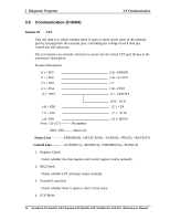
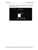
3 Diagnostic Programs 3.9 Communication 3.9 Communication (COMM) Subtest 01 LPT This test item is to check whether there is open or short circuit issue in the external pins by looping back the external pins, controlling the voltage of each data pin, control pin and status pin. The test requires an external connector to insert into the tested LPT port. Below is the connector's description. Fixture Description: (9) + PD7 (8) + PD6 (7) + PD5 (6) + PD4 (5) + PD3 (15) -ERROR (14) -AUTFD (13) (16) -PINIT (1) - STROBE (4) + PD2 (3) + PD1 (2) +PD0 Note: (1)~(17) -------- Pin number (10) - ACK (12) + PE (17) - SLIN (11)+ BUSY PD0~ PD7--------Data Line Status Line -------- -ERROR(S3), +SELECT(S4), -ACK(S6), +PE(S5), +BUSY(S7) Control Line -------- -AUTFD(C1), -PINIT(C2), -STROBE(C0), -SLIN(C3) 1. Register Check Check whether the data register and control register works normally. 2. IRQ Check Check whether LPT interrupt works normally. 3. External Loop back Check whether there is open or short circuit issue. 4. ECP Mode 54 dynabook AX/Satellite AW2/Equium A60/Satellite A60/ Satellite Pro A60 A65 Maintenance Manual
-
 1
1 -
2
-
3
-
4
-
5
-
6
-
7
-
8
-
9
-
10
-
11
-
12
-
13
-
14
-
15
-
16
-
17
-
18
-
19
-
20
-
21
-
22
-
23
-
24
-
25
-
26
-
27
-
28
-
29
-
30
-
31
-
32
-
33
-
34
-
35
-
36
-
37
-
38
-
39
-
40
-
41
-
42
-
43
-
44
-
45
-
46
-
47
-
48
-
49
-
50
-
51
-
52
-
53
-
54
-
55
-
56
-
57
-
58
-
59
-
60
-
61
-
62
-
63
-
64
-
65
-
66
-
67
-
68
-
69
-
70
-
71
-
72
-
73
-
74
-
75
-
76
-
77
-
78
-
79
-
80
-
81
-
82
-
83
-
84
-
85
-
86
-
87
-
88
-
89
-
90
-
91
-
92
-
93
-
94
-
95
-
96
-
97
-
98
-
99
-
100
-
101
-
102
-
103
-
104
-
105
-
106
-
107
-
108
-
109
-
110
-
111
-
112
-
113
-
114
-
115
-
116
-
117
-
118
-
 119
119 -
 120
120 -
 121
121 -
 122
122 -
 123
123 -
 124
124 -
 125
125 -
 126
126 -
 127
127 -
 128
128 -
 129
129 -
130
-
131
-
132
-
133
-
134
-
135
-
136
-
137
-
138
-
139
-
140
-
141
-
142
-
143
-
144
-
145
-
146
-
147
-
148
-
149
-
150
-
151
-
152
-
153
-
154
-
155
-
156
-
157
-
158
-
159
-
160
-
161
-
162
-
163
-
164
-
165
-
166
-
167
-
168
-
169
-
170
-
171
-
172
-
173
-
174
-
175
-
176
-
177
-
178
-
179
-
180
-
181
-
182
-
183
-
184
-
185
-
186
-
187
-
188
-
189
-
190
-
191
-
192
-
193
-
194
-
195
-
196
-
197
-
198
-
199
-
200
-
201
-
202
-
203
-
204
-
205
-
206
-
207
-
208
-
209
-
210
-
211
-
212
-
213
-
214
-
215
-
216
-
217
-
218
-
219
-
220
-
221
-
222
-
223
-
224
-
225
-
226
-
227
-
228
-
229
-
230
-
231
-
232
-
233
-
234
-
235
-
236
-
237
-
238
-
239
-
240
-
241
-
242
-
243
-
244
-
245
-
246
-
247
-
248
-
249
-
250
-
251
-
252
-
253
-
254
-
255
-
256
-
257
-
258
-
259
-
260
-
261
-
262
 |
 |