Toshiba A60 S1591 Maintenance Manual - Page 178
Replacement Procedures, 8 Top Cover, CAUTION, Installing the Top cover
 |
UPC - 032017268067
View all Toshiba A60 S1591 manuals
Add to My Manuals
Save this manual to your list of manuals |
Page 178 highlights
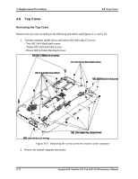
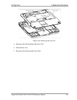
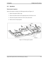
4 Replacement Procedures 4.8 Top Cover Installing the Top cover Install the top cover with the display assembly according to the following procedures and Figures 421, 4-22. 1. Connect the lid switch flat cables to CN23 on the system board. 2. Place the top cover, adjusting its position. CAUTION: Use care to avoid that the lid switch cable for lid switch is caught between the top cover and base body. 3. Connect the LED board flat cable to CN17 on the system board. 4. Turn the computer upside down and fix it with the following 25 screws: - Two M2.5x14 black bind screws - Twelve M2.5x8 black bind screws - Eleven M2.5x3 black flat-head screws 4-34 Equium A60/ Satellite A60/ Pro A60/ A65 Maintenance Manual
-
 1
1 -
2
-
3
-
4
-
5
-
6
-
7
-
8
-
9
-
10
-
11
-
12
-
13
-
14
-
15
-
16
-
17
-
18
-
19
-
20
-
21
-
22
-
23
-
24
-
25
-
26
-
27
-
28
-
29
-
30
-
31
-
32
-
33
-
34
-
35
-
36
-
37
-
38
-
39
-
40
-
41
-
42
-
43
-
44
-
45
-
46
-
47
-
48
-
49
-
50
-
51
-
52
-
53
-
54
-
55
-
56
-
57
-
58
-
59
-
60
-
61
-
62
-
63
-
64
-
65
-
66
-
67
-
68
-
69
-
70
-
71
-
72
-
73
-
74
-
75
-
76
-
77
-
78
-
79
-
80
-
81
-
82
-
83
-
84
-
85
-
86
-
87
-
88
-
89
-
90
-
91
-
92
-
93
-
94
-
95
-
96
-
97
-
98
-
99
-
100
-
101
-
102
-
103
-
104
-
105
-
106
-
107
-
108
-
109
-
110
-
111
-
112
-
113
-
114
-
115
-
116
-
117
-
118
-
119
-
120
-
121
-
122
-
123
-
124
-
125
-
126
-
127
-
128
-
129
-
130
-
131
-
132
-
133
-
134
-
135
-
136
-
137
-
138
-
139
-
140
-
141
-
142
-
143
-
144
-
145
-
146
-
147
-
148
-
149
-
150
-
151
-
152
-
153
-
154
-
155
-
156
-
157
-
158
-
159
-
160
-
161
-
162
-
163
-
164
-
165
-
166
-
167
-
168
-
169
-
170
-
171
-
172
-
 173
173 -
 174
174 -
 175
175 -
 176
176 -
 177
177 -
 178
178 -
 179
179 -
 180
180 -
 181
181 -
 182
182 -
 183
183 -
184
-
185
-
186
-
187
-
188
-
189
-
190
-
191
-
192
-
193
-
194
-
195
-
196
-
197
-
198
-
199
-
200
-
201
-
202
-
203
-
204
-
205
-
206
-
207
-
208
-
209
-
210
-
211
-
212
-
213
-
214
-
215
-
216
-
217
-
218
-
219
-
220
-
221
-
222
-
223
-
224
-
225
-
226
-
227
-
228
-
229
-
230
-
231
-
232
-
233
-
234
-
235
-
236
-
237
-
238
-
239
-
240
-
241
-
242
-
243
-
244
-
245
-
246
-
247
-
248
-
249
-
250
-
251
-
252
-
253
-
254
-
255
-
256
-
257
-
258
-
259
-
260
-
261
-
262
 |
 |
4
Replacement Procedures
4.8 Top Cover
4-34
Equium A60/ Satellite A60/ Pro A60/ A65 Maintenance Manual
Installing the Top cover
Install the top cover with the display assembly according to the following procedures and Figures 4-
21, 4-22.
1.
Connect the lid switch flat cables to CN23 on the system board.
2.
Place the top cover, adjusting its position.
CAUTION
: Use care to avoid that the lid switch cable for lid switch
is caught between
the top cover and base body.
3.
Connect the LED board flat cable to CN17 on the system board.
4.
Turn the computer upside down and fix it with the following 25 screws:
- Two M2.5x14 black bind screws
- Twelve M2.5x8 black bind screws
- Eleven M2.5x3 black flat-head screws