Toshiba A60 S1591 Maintenance Manual - Page 156
Removing the Optional Memory, Remove the memory cover.
 |
UPC - 032017268067
View all Toshiba A60 S1591 manuals
Add to My Manuals
Save this manual to your list of manuals |
Page 156 highlights
4 Replacement Procedures 4.1 General Removing the Optional Memory Remove the optional memory (module) according to the following procedures and Figures 4-4 and 4-5, after checking that the computer is turned off in boot mode. CAUTION: Remove the optional memory after turning off the computer. If this is violated, the computer or memory can be damaged. 1. Turn the computer upside down. 2. Release one M2.5x4 black bind screw. 3. Remove the memory cover. CAUTION: Do not touch the connectors on the memory modules or in the computer. Contaminated connectors can cause memory access problems. M2.5x4 black bind screw Memonry cover Figure 4-4 Removing the memory cover 4-12 Equium A60/ Satellite A60/ Pro A60/ A65 Maintenance Manual
-
 1
1 -
2
-
3
-
4
-
5
-
6
-
7
-
8
-
9
-
10
-
11
-
12
-
13
-
14
-
15
-
16
-
17
-
18
-
19
-
20
-
21
-
22
-
23
-
24
-
25
-
26
-
27
-
28
-
29
-
30
-
31
-
32
-
33
-
34
-
35
-
36
-
37
-
38
-
39
-
40
-
41
-
42
-
43
-
44
-
45
-
46
-
47
-
48
-
49
-
50
-
51
-
52
-
53
-
54
-
55
-
56
-
57
-
58
-
59
-
60
-
61
-
62
-
63
-
64
-
65
-
66
-
67
-
68
-
69
-
70
-
71
-
72
-
73
-
74
-
75
-
76
-
77
-
78
-
79
-
80
-
81
-
82
-
83
-
84
-
85
-
86
-
87
-
88
-
89
-
90
-
91
-
92
-
93
-
94
-
95
-
96
-
97
-
98
-
99
-
100
-
101
-
102
-
103
-
104
-
105
-
106
-
107
-
108
-
109
-
110
-
111
-
112
-
113
-
114
-
115
-
116
-
117
-
118
-
119
-
120
-
121
-
122
-
123
-
124
-
125
-
126
-
127
-
128
-
129
-
130
-
131
-
132
-
133
-
134
-
135
-
136
-
137
-
138
-
139
-
140
-
141
-
142
-
143
-
144
-
145
-
146
-
147
-
148
-
149
-
150
-
 151
151 -
 152
152 -
 153
153 -
 154
154 -
 155
155 -
 156
156 -
 157
157 -
 158
158 -
 159
159 -
 160
160 -
 161
161 -
162
-
163
-
164
-
165
-
166
-
167
-
168
-
169
-
170
-
171
-
172
-
173
-
174
-
175
-
176
-
177
-
178
-
179
-
180
-
181
-
182
-
183
-
184
-
185
-
186
-
187
-
188
-
189
-
190
-
191
-
192
-
193
-
194
-
195
-
196
-
197
-
198
-
199
-
200
-
201
-
202
-
203
-
204
-
205
-
206
-
207
-
208
-
209
-
210
-
211
-
212
-
213
-
214
-
215
-
216
-
217
-
218
-
219
-
220
-
221
-
222
-
223
-
224
-
225
-
226
-
227
-
228
-
229
-
230
-
231
-
232
-
233
-
234
-
235
-
236
-
237
-
238
-
239
-
240
-
241
-
242
-
243
-
244
-
245
-
246
-
247
-
248
-
249
-
250
-
251
-
252
-
253
-
254
-
255
-
256
-
257
-
258
-
259
-
260
-
261
-
262
 |
 |
4
Replacement Procedures
4.1
General
4-12
Equium A60/ Satellite A60/ Pro A60/ A65
Maintenance Manual
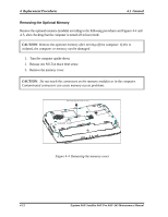
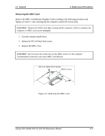
Removing the Optional Memory
Remove the optional memory (module) according to the following procedures and Figures 4-4 and
4-5, after checking that the computer is turned off in boot mode.
CAUTION
: Remove the optional memory after turning off the computer. If this is
violated, the computer or memory can be damaged.
1.
Turn the computer upside down.
2.
Release one M2.5x4 black bind screw.
3.
Remove the memory cover.
CAUTION
: Do not touch the connectors on the memory modules or in the computer.
Contaminated connectors can cause memory access problems.
M2.5x4 black bind screw
Memonry cover
Figure 4-4
Removing the memory cover