Toshiba A60 S1591 Maintenance Manual - Page 145
General, For removing the LCD Module
 |
UPC - 032017268067
View all Toshiba A60 S1591 manuals
Add to My Manuals
Save this manual to your list of manuals |
Page 145 highlights
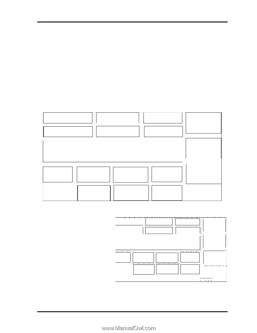
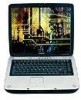
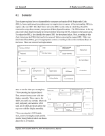
4.1 General 4 Replacement Procedures 4 1 4.1 General This chapter explains how to disassemble the computer and replace Field Replaceable Units (FRUs). Some replacement procedures may not require you to remove all the surrounding FRUs to replace only one FRU. The chart below shows the FRUs in the order in which they should be removed in a top-down manner, irrespective of their physical locations. The FRUs shown in the top area of the chart should normally be removed before removing the FRUs shown in the bottom area. To replace the FRUs, first identify the suspect FRU for the system failure. Next, according to this chart, determine the FRUs that need to be removed before removing the suspect FRU. After you determined those FRUs, go to the appropriate sections according to the section numbers shown in the boxes. Then start removal and replacement 4. 2 Wireless LAN Card 4. 5 Keyboard 4. 3 HDD 4. 6 ODD Bay Module 4. 4 Switch cover and Hotkey Board 4. 7 Display Assembly 4. 14 Display Mask 4.8 Top Cover 4. 15 FL Inverter Board 4. 9 Speakers 4. 10 Cooling Module 4. 11 CPU 4. 12 System Board 4.13 Cooling Module 4. 17 LED Board 4. 16 LCD Modules 4. 18 Touch Pad Board How to use the chart (two examples): 4. 2 Wireless LAN Card ? For removing the System Board 4.5 Keyboard First, remove the top cover with the 4.8 display assembly. Then, remove the Top Cover HDD, selectable bay module, Bluetooth 4. 3 HDD 4. 6 ODD Bay Module 4.4 Switchcoverand Hotkey Board 4. 7 Display Assembly card, keyboard, and wireless LAN 4.9 Speakers card, all of which are shown above the 4. 10 Cooling Module 4. 12 System Board 4. 17 LED Board top cover with the display assembly. 4. 11 CPU 4.13 North Bridge THermal Module 4. 18 Touch Pad Board ? For removing the LCD Module First, remove the display mask and FL inverter board, both of which are shown above the LCD module. 4. 14 Display Mask 4. 15 FL Inverter Board 4. 16 LCD Modules System Board LCD Module Equium A60/ Satellite A60/ Pro A60/ A65 Maintenance Manual 4-1
-
 1
1 -
2
-
3
-
4
-
5
-
6
-
7
-
8
-
9
-
10
-
11
-
12
-
13
-
14
-
15
-
16
-
17
-
18
-
19
-
20
-
21
-
22
-
23
-
24
-
25
-
26
-
27
-
28
-
29
-
30
-
31
-
32
-
33
-
34
-
35
-
36
-
37
-
38
-
39
-
40
-
41
-
42
-
43
-
44
-
45
-
46
-
47
-
48
-
49
-
50
-
51
-
52
-
53
-
54
-
55
-
56
-
57
-
58
-
59
-
60
-
61
-
62
-
63
-
64
-
65
-
66
-
67
-
68
-
69
-
70
-
71
-
72
-
73
-
74
-
75
-
76
-
77
-
78
-
79
-
80
-
81
-
82
-
83
-
84
-
85
-
86
-
87
-
88
-
89
-
90
-
91
-
92
-
93
-
94
-
95
-
96
-
97
-
98
-
99
-
100
-
101
-
102
-
103
-
104
-
105
-
106
-
107
-
108
-
109
-
110
-
111
-
112
-
113
-
114
-
115
-
116
-
117
-
118
-
119
-
120
-
121
-
122
-
123
-
124
-
125
-
126
-
127
-
128
-
129
-
130
-
131
-
132
-
133
-
134
-
135
-
136
-
137
-
138
-
139
-
 140
140 -
 141
141 -
 142
142 -
 143
143 -
 144
144 -
 145
145 -
 146
146 -
 147
147 -
 148
148 -
 149
149 -
 150
150 -
151
-
152
-
153
-
154
-
155
-
156
-
157
-
158
-
159
-
160
-
161
-
162
-
163
-
164
-
165
-
166
-
167
-
168
-
169
-
170
-
171
-
172
-
173
-
174
-
175
-
176
-
177
-
178
-
179
-
180
-
181
-
182
-
183
-
184
-
185
-
186
-
187
-
188
-
189
-
190
-
191
-
192
-
193
-
194
-
195
-
196
-
197
-
198
-
199
-
200
-
201
-
202
-
203
-
204
-
205
-
206
-
207
-
208
-
209
-
210
-
211
-
212
-
213
-
214
-
215
-
216
-
217
-
218
-
219
-
220
-
221
-
222
-
223
-
224
-
225
-
226
-
227
-
228
-
229
-
230
-
231
-
232
-
233
-
234
-
235
-
236
-
237
-
238
-
239
-
240
-
241
-
242
-
243
-
244
-
245
-
246
-
247
-
248
-
249
-
250
-
251
-
252
-
253
-
254
-
255
-
256
-
257
-
258
-
259
-
260
-
261
-
262
 |
 |