Toshiba A60 S1591 Maintenance Manual - Page 50
System Board, Message Check
 |
UPC - 032017268067
View all Toshiba A60 S1591 manuals
Add to My Manuals
Save this manual to your list of manuals |
Page 50 highlights
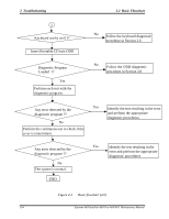
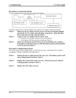
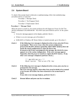
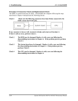
2.4 System Board 2 Troubleshooting 2.4 System Board To check if the system board is defective or malfunctioning, follow the troubleshooting procedures below as instructed. Procedure 1 Message Check Procedure 2 Test Program Check Procedure 3 Replacement Check Procedure 1 Message Check When the power is turned on, the system performs the self-diagnostic Power On Self Test (POST) embedded in the BIOS ROM. The POST tests and initializes each IC on the system board. ? If an error message appears on the display, perform Check 1. ? If there is no error message, go to Procedure 2. ? If MS-DOS or Windows XP Home Edition is loaded normally, go to Procedure 3. Check 1 If the following error message is displayed on the screen, press the F1 key as prompted. These errors occur when the system configuration preserved in the RTC memory (generally called CMOS memory) does not match the actual configuration or when the data is lost. If you press the F1 key as prompted by the message, the TSETUP screen appears to set the system configuration. If the error message appears frequently when the power is turned on, replace the RTC battery. If any other error message is displayed, perform Check 2. *** Bad RTC battery *** Check system. Then press [F1] key Check 2 Check 3 If the following error message is displayed on the screen, press any key as prompted by the message. The error message appears when either data stored in RAM to be resumed is lost because the battery has been exhausted or the system board is faulty. If any other error message displays, perform Check 3. Resume failure and press any key to continue . Equium A60/Satellite A60/ Pro A60/A65 Maintenance Manual 2-9
-
 1
1 -
2
-
3
-
4
-
5
-
6
-
7
-
8
-
9
-
10
-
11
-
12
-
13
-
14
-
15
-
16
-
17
-
18
-
19
-
20
-
21
-
22
-
23
-
24
-
25
-
26
-
27
-
28
-
29
-
30
-
31
-
32
-
33
-
34
-
35
-
36
-
37
-
38
-
39
-
40
-
41
-
42
-
43
-
44
-
 45
45 -
 46
46 -
 47
47 -
 48
48 -
 49
49 -
 50
50 -
 51
51 -
 52
52 -
 53
53 -
 54
54 -
 55
55 -
56
-
57
-
58
-
59
-
60
-
61
-
62
-
63
-
64
-
65
-
66
-
67
-
68
-
69
-
70
-
71
-
72
-
73
-
74
-
75
-
76
-
77
-
78
-
79
-
80
-
81
-
82
-
83
-
84
-
85
-
86
-
87
-
88
-
89
-
90
-
91
-
92
-
93
-
94
-
95
-
96
-
97
-
98
-
99
-
100
-
101
-
102
-
103
-
104
-
105
-
106
-
107
-
108
-
109
-
110
-
111
-
112
-
113
-
114
-
115
-
116
-
117
-
118
-
119
-
120
-
121
-
122
-
123
-
124
-
125
-
126
-
127
-
128
-
129
-
130
-
131
-
132
-
133
-
134
-
135
-
136
-
137
-
138
-
139
-
140
-
141
-
142
-
143
-
144
-
145
-
146
-
147
-
148
-
149
-
150
-
151
-
152
-
153
-
154
-
155
-
156
-
157
-
158
-
159
-
160
-
161
-
162
-
163
-
164
-
165
-
166
-
167
-
168
-
169
-
170
-
171
-
172
-
173
-
174
-
175
-
176
-
177
-
178
-
179
-
180
-
181
-
182
-
183
-
184
-
185
-
186
-
187
-
188
-
189
-
190
-
191
-
192
-
193
-
194
-
195
-
196
-
197
-
198
-
199
-
200
-
201
-
202
-
203
-
204
-
205
-
206
-
207
-
208
-
209
-
210
-
211
-
212
-
213
-
214
-
215
-
216
-
217
-
218
-
219
-
220
-
221
-
222
-
223
-
224
-
225
-
226
-
227
-
228
-
229
-
230
-
231
-
232
-
233
-
234
-
235
-
236
-
237
-
238
-
239
-
240
-
241
-
242
-
243
-
244
-
245
-
246
-
247
-
248
-
249
-
250
-
251
-
252
-
253
-
254
-
255
-
256
-
257
-
258
-
259
-
260
-
261
-
262
 |
 |