Toshiba A60 S1591 Maintenance Manual - Page 190
Replacement Procedures, 13 North Bridge Thermal Module, MDC cable, CN500, Mylar
 |
UPC - 032017268067
View all Toshiba A60 S1591 manuals
Add to My Manuals
Save this manual to your list of manuals |
Page 190 highlights
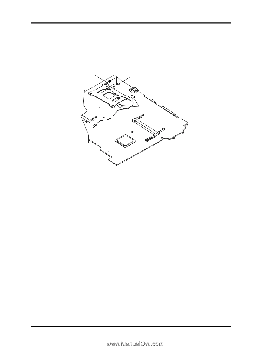
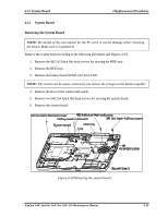
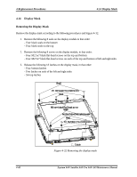
4 Replacement Procedures 4.13 North Bridge Thermal Module 8. Remove two pieces of sticky Mylar securing the MDC cable. 9. Disconnect the MDC cable from CN500 on the system board. 10. Remove the MDC cable. MDC cable CN500 Mylar Figure 4-31 Removing the MDC cable Installing the Removing North Bridge thermal module and MDC cable Install the Removing North Bridge thermal module according to the following procedures and Figure 4-30, 4-31. 1. Place the MDC cable in the correct position... 2. Connect the MDC cable from CN500 on the system board. 3. Stick two pieces of sticky Mylar securing the MDC cable. 4. Connect the North Bridge thermal module cable to the CN15 on the system board. 5. Place the North Bridge thermal module in the correct position. 6. Secure the two washers and M2x3 black bind screws. 7. Place the CD tray in the correct position. 8. Secure the one M2.5x2.5 white bind screws. 4-46 Equium A60/ Satellite A60/ Pro A60/ A65 Maintenance Manual
-
 1
1 -
2
-
3
-
4
-
5
-
6
-
7
-
8
-
9
-
10
-
11
-
12
-
13
-
14
-
15
-
16
-
17
-
18
-
19
-
20
-
21
-
22
-
23
-
24
-
25
-
26
-
27
-
28
-
29
-
30
-
31
-
32
-
33
-
34
-
35
-
36
-
37
-
38
-
39
-
40
-
41
-
42
-
43
-
44
-
45
-
46
-
47
-
48
-
49
-
50
-
51
-
52
-
53
-
54
-
55
-
56
-
57
-
58
-
59
-
60
-
61
-
62
-
63
-
64
-
65
-
66
-
67
-
68
-
69
-
70
-
71
-
72
-
73
-
74
-
75
-
76
-
77
-
78
-
79
-
80
-
81
-
82
-
83
-
84
-
85
-
86
-
87
-
88
-
89
-
90
-
91
-
92
-
93
-
94
-
95
-
96
-
97
-
98
-
99
-
100
-
101
-
102
-
103
-
104
-
105
-
106
-
107
-
108
-
109
-
110
-
111
-
112
-
113
-
114
-
115
-
116
-
117
-
118
-
119
-
120
-
121
-
122
-
123
-
124
-
125
-
126
-
127
-
128
-
129
-
130
-
131
-
132
-
133
-
134
-
135
-
136
-
137
-
138
-
139
-
140
-
141
-
142
-
143
-
144
-
145
-
146
-
147
-
148
-
149
-
150
-
151
-
152
-
153
-
154
-
155
-
156
-
157
-
158
-
159
-
160
-
161
-
162
-
163
-
164
-
165
-
166
-
167
-
168
-
169
-
170
-
171
-
172
-
173
-
174
-
175
-
176
-
177
-
178
-
179
-
180
-
181
-
182
-
183
-
184
-
 185
185 -
 186
186 -
 187
187 -
 188
188 -
 189
189 -
 190
190 -
 191
191 -
 192
192 -
 193
193 -
 194
194 -
 195
195 -
196
-
197
-
198
-
199
-
200
-
201
-
202
-
203
-
204
-
205
-
206
-
207
-
208
-
209
-
210
-
211
-
212
-
213
-
214
-
215
-
216
-
217
-
218
-
219
-
220
-
221
-
222
-
223
-
224
-
225
-
226
-
227
-
228
-
229
-
230
-
231
-
232
-
233
-
234
-
235
-
236
-
237
-
238
-
239
-
240
-
241
-
242
-
243
-
244
-
245
-
246
-
247
-
248
-
249
-
250
-
251
-
252
-
253
-
254
-
255
-
256
-
257
-
258
-
259
-
260
-
261
-
262
 |
 |