Toshiba A60 S1591 Maintenance Manual - Page 49
Troubleshooting, Power Supply, Procedure 2, Connection Check, Replacement Check
 |
UPC - 032017268067
View all Toshiba A60 S1591 manuals
Add to My Manuals
Save this manual to your list of manuals |
Page 49 highlights
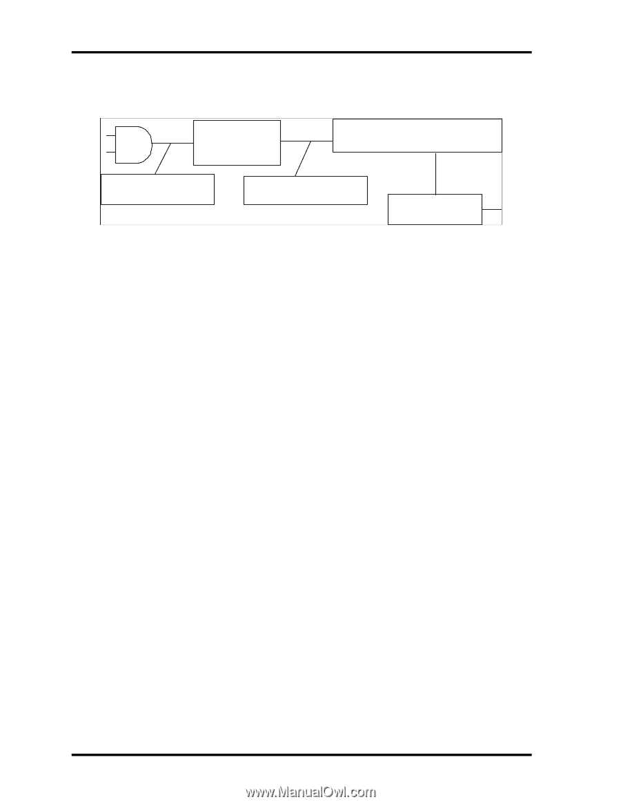
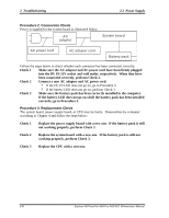
2 Troubleshooting 2.3 Power Supply Procedure 2 Connection Check Power is supplied to the system board as illustrated below: AC adaptor System board AC power cord AC adaptor cord Battery pack Follow the steps below to check whether each connector has been connected correctly: Check 1 Make sure the AC adaptor and AC power cord have been firmly plugged into the DC IN 15V socket and wall outlet, respectively. When they have been connected correctly, perform Check 2. Check 2 Connect a new AC adaptor and AC power cord. ? If the DC IN LED does not go on, go to Procedure 3. ? If the battery LED does not go on, perform Check 3. Check 3 Make sure the battery pack has been correctly installed in the computer. If the battery LED does not go on while the battery pack has been installed correctly, go to Procedure 3. Procedure 3 Replacement Check The system board, power supply board, or CPU may be faulty. Disassemble the computer according to Chapter 4 and follow the steps below: Check 1 Replace the power supply board with a new one. If the battery pack is still not working properly, perform Check 2. Check 2 Replace the system board with a new one. If the battery pack is still not working properly, perform Check 3. Check 3 Replace the CPU with a new one. 2-8 Equium A60/Satellite A60/ Pro A60/A65 Maintenance Manual
-
 1
1 -
2
-
3
-
4
-
5
-
6
-
7
-
8
-
9
-
10
-
11
-
12
-
13
-
14
-
15
-
16
-
17
-
18
-
19
-
20
-
21
-
22
-
23
-
24
-
25
-
26
-
27
-
28
-
29
-
30
-
31
-
32
-
33
-
34
-
35
-
36
-
37
-
38
-
39
-
40
-
41
-
42
-
43
-
 44
44 -
 45
45 -
 46
46 -
 47
47 -
 48
48 -
 49
49 -
 50
50 -
 51
51 -
 52
52 -
 53
53 -
 54
54 -
55
-
56
-
57
-
58
-
59
-
60
-
61
-
62
-
63
-
64
-
65
-
66
-
67
-
68
-
69
-
70
-
71
-
72
-
73
-
74
-
75
-
76
-
77
-
78
-
79
-
80
-
81
-
82
-
83
-
84
-
85
-
86
-
87
-
88
-
89
-
90
-
91
-
92
-
93
-
94
-
95
-
96
-
97
-
98
-
99
-
100
-
101
-
102
-
103
-
104
-
105
-
106
-
107
-
108
-
109
-
110
-
111
-
112
-
113
-
114
-
115
-
116
-
117
-
118
-
119
-
120
-
121
-
122
-
123
-
124
-
125
-
126
-
127
-
128
-
129
-
130
-
131
-
132
-
133
-
134
-
135
-
136
-
137
-
138
-
139
-
140
-
141
-
142
-
143
-
144
-
145
-
146
-
147
-
148
-
149
-
150
-
151
-
152
-
153
-
154
-
155
-
156
-
157
-
158
-
159
-
160
-
161
-
162
-
163
-
164
-
165
-
166
-
167
-
168
-
169
-
170
-
171
-
172
-
173
-
174
-
175
-
176
-
177
-
178
-
179
-
180
-
181
-
182
-
183
-
184
-
185
-
186
-
187
-
188
-
189
-
190
-
191
-
192
-
193
-
194
-
195
-
196
-
197
-
198
-
199
-
200
-
201
-
202
-
203
-
204
-
205
-
206
-
207
-
208
-
209
-
210
-
211
-
212
-
213
-
214
-
215
-
216
-
217
-
218
-
219
-
220
-
221
-
222
-
223
-
224
-
225
-
226
-
227
-
228
-
229
-
230
-
231
-
232
-
233
-
234
-
235
-
236
-
237
-
238
-
239
-
240
-
241
-
242
-
243
-
244
-
245
-
246
-
247
-
248
-
249
-
250
-
251
-
252
-
253
-
254
-
255
-
256
-
257
-
258
-
259
-
260
-
261
-
262
 |
 |