Toshiba Portege R400 PPR40C Users Manual Canada; English - Page 56
up to release latches and remove the keyboard brace., Lift up the back of the keyboard
 |
View all Toshiba Portege R400 PPR40C manuals
Add to My Manuals
Save this manual to your list of manuals |
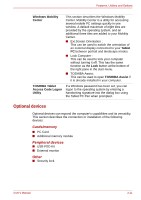
Page 56 highlights
Features, Utilities and Options 4. Turn your computer over. 5. Open the display panel. 6. Slip your finger under a notch at the end of the keyboard brace and lift up to release latches and remove the keyboard brace. Keyboard brace Figure 3-3 Removing the keyboard brace 7. Remove two screws securing the keyboard. Use a point size 0 Phillips screwdriver. 8. Lift up the back of the keyboard, rotate it toward you and lay in face down on the palm rest. ■ Never allow metal objects, such as screws, staples and paper clips, to enter the computer or keyboard. Foreign metal objects can create a short circuit, which can cause computer damage and fire, possibly resulting in serious injury. ■ When you move the keyboard forward, do not touch the keys. Doing so could cause misalignment. Hold the keyboard by the sides and lay it gently on the palm rest. ■ The keyboard is connected to the computer by a keyboard ribbon cable. Be careful not to apply tension to this cable when you lift up the keyboard. Do not try to disconnect this cable. Screws User's Manual Figure 3-4 Removing two screws and rotate the keyboard 3-16
-
 1
1 -
2
-
3
-
4
-
5
-
6
-
7
-
8
-
9
-
10
-
11
-
12
-
13
-
14
-
15
-
16
-
17
-
18
-
19
-
20
-
21
-
22
-
23
-
24
-
25
-
26
-
27
-
28
-
29
-
30
-
31
-
32
-
33
-
34
-
35
-
36
-
37
-
38
-
39
-
40
-
41
-
42
-
43
-
44
-
45
-
46
-
47
-
48
-
49
-
50
-
 51
51 -
 52
52 -
 53
53 -
 54
54 -
 55
55 -
 56
56 -
 57
57 -
 58
58 -
 59
59 -
 60
60 -
 61
61 -
62
-
63
-
64
-
65
-
66
-
67
-
68
-
69
-
70
-
71
-
72
-
73
-
74
-
75
-
76
-
77
-
78
-
79
-
80
-
81
-
82
-
83
-
84
-
85
-
86
-
87
-
88
-
89
-
90
-
91
-
92
-
93
-
94
-
95
-
96
-
97
-
98
-
99
-
100
-
101
-
102
-
103
-
104
-
105
-
106
-
107
-
108
-
109
-
110
-
111
-
112
-
113
-
114
-
115
-
116
-
117
-
118
-
119
-
120
-
121
-
122
-
123
-
124
-
125
-
126
-
127
-
128
-
129
-
130
-
131
-
132
-
133
-
134
-
135
-
136
-
137
-
138
-
139
-
140
-
141
-
142
-
143
-
144
-
145
-
146
-
147
-
148
-
149
-
150
-
151
-
152
-
153
-
154
-
155
-
156
-
157
-
158
-
159
-
160
-
161
-
162
-
163
-
164
-
165
-
166
-
167
-
168
-
169
-
170
-
171
-
172
-
173
-
174
-
175
-
176
-
177
-
178
-
179
-
180
-
181
-
182
-
183
-
184
-
185
-
186
-
187
-
188
-
189
-
190
 |
 |
