Yamaha CLP-611 Owner's Manual - Page 64
CLP-611 Assembly Procedure, Montage des CLP-611
 |
View all Yamaha CLP-611 manuals
Add to My Manuals
Save this manual to your list of manuals |
Page 64 highlights
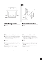
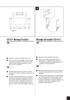
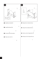
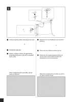
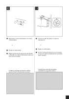
1 3 Six long golden screws 1 Sechs lange goldene Schrauben 1 Six longues vis dorées 1 Seis tornillos largos de oro 1 (5!40mm) Four tapered screws 4 Vier Senkkopfschrauben 4 Quatre vis pointues 4 Cuatro tornillos cónicos 4 (4!20mm) 2 Phone jacks Klinkenbuchsen Prises pour casque d'écoute Styrofoam pads Tomas de auriculares Styroporteile Coussinets en mousse Planchas de poliestireno Four medium roundhead screws 2 Two short roundhead screws 5 Vier mittlere Rundkopfschrauben 2 Zwei kurze Rundkopfschrauben 5 Quatre vis moyennes à tête ronde 2 Deux petites vis à tête ronde 5 Cuatro tornillos medianos de cabeza redonda 2 Dos tornillos cortos de cabeza redonda 5 (6!20mm) (4!12mm) Four medium flathead screws 3 Vier mittlere Flachkopfschrauben 3 Quatre vis moyennes à tête plate 3 Cuatro tornillos medianos de cabeza plana 3 (6!20mm) Two cord clamps 6 Zwei Kabelhalter 6 Deux pinces de fixation pour câbles 6 Dos bridas de cable 6 CLP-611 Assembly Procedure NOTE • Be careful not to confuse parts, and be sure to install all parts in the correct direction. Please assemble in accordance with the sequence given below. • Assembly should be carried out by at least two persons. • Be sure to use the correct screw sizes. Use of incorrect screws can cause damage. • Be sure to tighten up all screws upon completing assembly of each unit. • To disassemble, reverse the assembly sequence given below. 1 Have a Phillips-head screwdriver ready. 2 Open the box. Take out the two styrofoam pads and place them on the floor. Then take out main unit (A) and place it on top of the pads. NOTE Position the pads so as to protect the phone jacks on the base of the unit. 3 Remove all parts from the box. Confirm that all of the parts indicated above are present. 4 Fasten right sideboard (C) to right leg (G), and left sideboard (B) to left leg (F). In each case, join the board to the leg, aligning the notch on the metal fitting with the indentation on the leg. Fasten in place with the long gold screws 1. Montage des CLP-611 HINWEIS • Achten Sie darauf, die Teile nicht zu verwechseln, und installieren Sie alle Teile in der richtigen Ausrichtung. Gehen Sie beim Zusammenbau bitte in der angegebenen Reihenfolge vor. • Die Montage sollte von mindestens zwei Personen vorgenommen werden. • Achten Sie darauf, die richtige Schraubengröße zu verwenden. Die Verwendung der falschen Schrauben kann zu Schäden führen. • Achten Sie während der Montage darauf, bei jedem Arbeitsgang alle Schrauben festzuziehen. • Für die Demontage muß die angegebene Reihenfolge umgekehrt befolgt werden. 1 Halten Sie einen Kreuzschlitzschraubendreher bereit. 2 Öffnen Sie den Karton. Nehmen Sie die beiden Styroporteile heraus und legen Sie sie auf den Boden. Nehmen Sie dann die Haupteinheit (A) heraus, und legen Sie es auf die Styroporteile. HINWEIS Positionieren Sie die Styroporteile so, daß die Klinkenbuchsen am Boden des Gerätes geschützt sind. 3 Nehmen Sie alle Teile aus dem Karton. Sehen Sie nach, ob alle oben gezeigten Teile vorhanden sind. 4 Bringen Sie das rechte Seitenteil (C) am rechten Bein (G), das linke Seitenteil (B) am linken Bein (F) an. Verbinden Sie das Seitenteil mit dem Bein, indem Sie die Aussparung an dem Metallbeschlag mit der Vertiefung im Bein in Übereinstimmung bringen. Befestigen Sie es mit den langen Goldene Schrauben 1. 60 CLP-811/611 CLP-611 Assembly Procedure/Montage des CLP-611/CLP-611 Montage Procédure/Montaje del modelo CLP-611
-
 1
1 -
2
-
3
-
4
-
5
-
6
-
7
-
8
-
9
-
10
-
11
-
12
-
13
-
14
-
15
-
16
-
17
-
18
-
19
-
20
-
21
-
22
-
23
-
24
-
25
-
26
-
27
-
28
-
29
-
30
-
31
-
32
-
33
-
34
-
35
-
36
-
37
-
38
-
39
-
40
-
41
-
42
-
43
-
44
-
45
-
46
-
47
-
48
-
49
-
50
-
51
-
52
-
53
-
54
-
55
-
56
-
57
-
58
-
 59
59 -
 60
60 -
 61
61 -
 62
62 -
 63
63 -
 64
64 -
 65
65 -
 66
66 -
 67
67 -
 68
68 -
 69
69 -
70
-
71
-
72
 |
 |
