Yamaha MMP1 MMP1 Operation Manual [English] - Page 15
Sub screen
 |
View all Yamaha MMP1 manuals
Add to My Manuals
Save this manual to your list of manuals |
Page 15 highlights
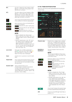
4-1-3. Sub screen This is the Sub screen used for monitor control. NOTE You can use this screen when logged in as an "Administrator" or "Advanced User." Meters Displays Monitor Matrix Out meters 4. Screens Monitor section For adjusting input source and Send levels Oscillator section For selecting signals to output from the oscillator, and adjusting their output levels Snapshot section For storing and recalling Snapshots Talkback section For selecting Talkback interrupt destinations and adjusting Talkback output levels 4-1-3a. Meters Here you can display Monitor Matrix Out meters. These channels include Monitor outputs (up to 32 ch), Downmix L/R, and Headphone L/R. NOTE • The meters shown here are the same as those on the Main screen. • Drag a Main Monitor Out meter to change the order. Values less than -20 dB are displayed in green , values less than 0 dB in yellow , and values equal to or above 0 in red . Peak hold circuits are not displayed. NOTE • The breakdown of Monitor outputs is based on the format selected under "Monitor Matrix Out" in the "Monitor Matrix" tab of the "Scene" tab on the Settings screen. • The signal position displayed on the meters can be selected in the "System" tab of the "Scene" tab on the Settings screen. Click these buttons to set all Main Monitor outputs to SOLO or MUTE. / Click these buttons to turn each Main Monitor SOLO or MUTE setting on (lights up) or off. Click these buttons to turn the oscillator on (lit) or off. You can select the oscillator type used in the "Oscillator" section on the Sub screen. represents sine waves and represents pink noise. This is displayed when using Talkback. MMP1 Operation Manual 15
-
 1
1 -
2
-
3
-
4
-
5
-
6
-
7
-
8
-
9
-
 10
10 -
 11
11 -
 12
12 -
 13
13 -
 14
14 -
 15
15 -
 16
16 -
 17
17 -
 18
18 -
 19
19 -
 20
20 -
21
-
22
-
23
-
24
-
25
-
26
-
27
-
28
-
29
-
30
-
31
-
32
-
33
-
34
-
35
-
36
-
37
-
38
-
39
-
40
-
41
-
42
-
43
-
44
-
45
-
46
-
47
-
48
-
49
-
50
-
51
-
52
-
53
-
54
-
55
-
56
-
57
-
58
-
59
-
60
-
61
-
62
-
63
-
64
-
65
-
66
-
67
-
68
 |
 |
