Yamaha MMP1 MMP1 Operation Manual [English] - Page 63
Lighting up the On Air sign, when the mic is on by using the, GPI output
 |
View all Yamaha MMP1 manuals
Add to My Manuals
Save this manual to your list of manuals |
Page 63 highlights
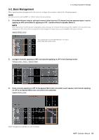
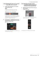
2. Assign Studio Speaker output destinations. Patch screen - Output Patch 5. Configuring System Settings 5-4-3. Lighting up the "On Air" sign when the mic is on by using the GPI output Settings screen - Global - GPI In the example shown in the image above, the L/R sources for the selected STU 1 format are assigned to AES/EBU Out 1/2 to which the recording booth speakers are connected. 3. Mute Studio Speaker output automatically when the mic is on. Settings screen - Scene - System In the example shown in the image above, pin 1 on the GPI [OUTPUT] connector is set to connect with the GPI input pin for the "On Air" sign. Muting the channel strip 1 mic will form a pin 1 connection for the GPI [OUTPUT] connector. The parameter "1" signifies channel strip 1. In the example shown in the image above, STU1 output is set to be muted when the channel strip 1 mic is on. MMP1 Operation Manual 63
-
 1
1 -
2
-
3
-
4
-
5
-
6
-
7
-
8
-
9
-
10
-
11
-
12
-
13
-
14
-
15
-
16
-
17
-
18
-
19
-
20
-
21
-
22
-
23
-
24
-
25
-
26
-
27
-
28
-
29
-
30
-
31
-
32
-
33
-
34
-
35
-
36
-
37
-
38
-
39
-
40
-
41
-
42
-
43
-
44
-
45
-
46
-
47
-
48
-
49
-
50
-
51
-
52
-
53
-
54
-
55
-
56
-
57
-
 58
58 -
 59
59 -
 60
60 -
 61
61 -
 62
62 -
 63
63 -
 64
64 -
 65
65 -
 66
66 -
 67
67 -
 68
68
 |
 |
