Yamaha MMP1 MMP1 Operation Manual [English] - Page 62
Commentary functions
 |
View all Yamaha MMP1 manuals
Add to My Manuals
Save this manual to your list of manuals |
Page 62 highlights
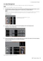
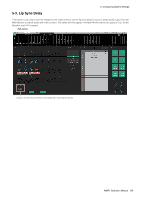
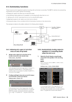
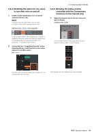
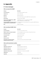
5. Configuring System Settings 5-4. Commentary functions These functions are for equipment used for recording with commentary functionality. The MMP1's internal voice processing functionality can be used to perform the following. • Allowing mic users to turn their mics on and off by hand • Automatically muting output sent to speakers in a recording booth when the mic is on • Lighting up the "On Air" sign when the mic is on by using the GPI output • Disabling the option for mic users to turn their mics on and off • Showing the status of mics controlled with the Commentary functions on the channel strip This example is based on the system outlined in the following block diagram. Mute Cue Mix, Talkback (Studio Speaker 1) (AES/EBU Output 1) (Analog Input 1) Foot Controller, etc. (GPI Input 1) Recording Booth On Air (GPI Output 1) Mute Select (Channel Strip Input 1) Cough Mute Override function 5-4-1. Allowing mic users to turn their mics on and off by hand 1. Assign audio output from mics that can be turned on and off to the channel strip. Patch screen - Input Patch In the example shown in the image above, "Analog 1" is assigned to Channel Strip In 1-A because the mic preamp output is connected to the ANALOG [INPUT 1] connector on the MMP1. 2. Configure settings to turn mics on and off using a foot controller or other such device. Settings screen - Global - GPI 5-4-2. Automatically muting output to speakers in a recording booth when the mic is on 1. Select the Studio Speaker output format connected to the speakers in the recording booth. NOTE Set the connection with the MMP1 to "Offline" before changing settings. Settings screen - Scene - Monitor Matrix In the example shown in the image above, mic input into channel strip 1 will be muted when pin 1 on the GPI [INPUT] connector connected to the foot controller is set to "High." The parameter "1" signifies channel strip 1. In the example shown in the image above, "2" is selected as the Studio Speaker 1 format as the recording booth speakers used are stereo speakers. Here, "2" signifies two-channel audio (stereo). MMP1 Operation Manual 62
-
 1
1 -
2
-
3
-
4
-
5
-
6
-
7
-
8
-
9
-
10
-
11
-
12
-
13
-
14
-
15
-
16
-
17
-
18
-
19
-
20
-
21
-
22
-
23
-
24
-
25
-
26
-
27
-
28
-
29
-
30
-
31
-
32
-
33
-
34
-
35
-
36
-
37
-
38
-
39
-
40
-
41
-
42
-
43
-
44
-
45
-
46
-
47
-
48
-
49
-
50
-
51
-
52
-
53
-
54
-
55
-
56
-
 57
57 -
 58
58 -
 59
59 -
 60
60 -
 61
61 -
 62
62 -
 63
63 -
 64
64 -
 65
65 -
 66
66 -
 67
67 -
68
 |
 |
