Yamaha MT1X Owner's Manual - Page 11
Meter And Monitor Meter Select Switch, Peak Level Meters, Stereo Position, Trk Position
 |
View all Yamaha MT1X manuals
Add to My Manuals
Save this manual to your list of manuals |
Page 11 highlights
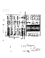
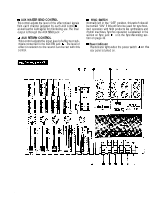
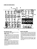
METER AND MONITOR SECTION ThisMswEiTtEcRh iSsEuLsEeCdTtoSWseIlTeCcHt the signal for level indication by the Peak Level Meters STEREO Position: The level of the signal output through the ST OUT jacks is indicated. The meter on the far left shows the level of the Left channel of the stereo signal, while the second meter from the left shows the level of the Right channel. Setting to this position during pingponging or mixdown operations enables easy reading of the recording level. 4 TRK Position: Set the switch in this position to display the level of each track. Starting from the far left, each meter corresponds to tracks 1-4. During playback, the playback level is displayed; during recording, the recording level is displayed. Setting the switch to this position during overdubbing enables easy reading of the recording level. 9 TherePEaAreK 1L4EVLEEDL iMndEicTEaRtoSrs in each meter which show a range from - 20dB to + 5dB. During recording, setting levels high (but below the point where the recording becomes distorted) will ensure the greatest dynamic range with the lowest possible noise. An ideal point is when the LED indicators for 0dB and above flash occasionally. During stereo signal level indication, the actual specified output from the ST OUT jacks is (at a 50K ohm load) when the LED indicators start to flash at 0dB.
-
 1
1 -
2
-
3
-
4
-
5
-
 6
6 -
 7
7 -
 8
8 -
 9
9 -
 10
10 -
 11
11 -
 12
12 -
 13
13 -
 14
14 -
 15
15 -
 16
16 -
17
-
18
-
19
-
20
-
21
-
22
-
23
-
24
-
25
-
26
-
27
-
28
-
29
-
30
-
31
-
32
-
33
-
34
-
35
-
36
-
37
-
38
-
39
-
40
-
41
-
42
 |
 |
