3Com 3CBLSG24 User Guide
3Com 3CBLSG24 - Baseline Switch 2924-SFP Manual
 |
View all 3Com 3CBLSG24 manuals
Add to My Manuals
Save this manual to your list of manuals |
3Com 3CBLSG24 manual content summary:
- 3Com 3CBLSG24 | User Guide - Page 1
3Com® Baseline Switch 2916-SFP Plus and Baseline Switch 2924-SFP Plus User Guide 3CBLSG16 / 3CBLSG24 www.3Com.com Part Number 10016143 Rev. AA Published May 2007 - 3Com 3CBLSG24 | User Guide - Page 2
to you in conjunction with, this User Guide. Unless otherwise indicated, 3Com registered trademarks are registered in the United States and may or may not be registered in other countries. 3Com and the 3Com logo are registered trademarks of 3Com Corporation. Intel and Pentium are registered - 3Com 3CBLSG24 | User Guide - Page 3
ABOUT THIS GUIDE User Guide Overview This guide provides information about the Web user interface for the 3Com® Baseline Switch 2916-SFP Plus and Baseline Switch 2924-SFP Plus. The Web interface is a network management system that allows you to configure, monitor, and troubleshoot your switch from - 3Com 3CBLSG24 | User Guide - Page 4
THIS GUIDE ■ a Local Area Network (LAN) which combine user stations and network devices into a single virtual Configuring IP and MAC Address Information - Provides information for configuring IP addresses, Quality of Service - Provides information defining Quality of Service, including DSCP - 3Com 3CBLSG24 | User Guide - Page 5
you to potential personal injury. Related Documentation In addition to this guide, other documentation available for the 3Com Baseline Switch 2916-SFP Plus/2924-SFP Plus include the following: ■ Safety and Support Information: Provides installation, set-up, and regulatory compliance information. - 3Com 3CBLSG24 | User Guide - Page 6
17 Methods of Managing a Switch 17 Switch Setup Overview 18 Using the Command Line Interface (CLI 21 Setting Up Web Interface Management 25 Setting Up SNMP Management V1 or V2 26 Default Users and Passwords 27 Upgrading Software using the CLI 27 2 USING THE 3COM WEB INTERFACE Starting the - 3Com 3CBLSG24 | User Guide - Page 7
3 VIEWING BASIC SETTINGS Viewing Device Settings 41 Viewing Color Keys 43 4 MANAGING DEVICE SECURITY Configuring System Access 45 Defining RADIUS Clients 50 Defining Port-Based Authentication (802.1X 52 Defining Access Control Lists 57 Enabling Broadcast Storm 78 5 GENERAL SYSTEM INFORMATION - 3Com 3CBLSG24 | User Guide - Page 8
107 Removing VLANs 108 9 CONFIGURING IP AND MAC ADDRESS INFORMATION Defining IP Addressing 109 Configuring ARP Settings 110 Configuring Defining SNMP Traps 139 Removing SNMP Traps 140 13 CONFIGURING QUALITY OF SERVICE Viewing CoS Settings 143 Defining CoS 144 Viewing CoS to Queue 145 - 3Com 3CBLSG24 | User Guide - Page 9
the Firmware Image 3Com Network Director 182 3Com Network Access Manager 182 3Com Enterprise Management Suite 183 Integration Kit with HP OpenView Network Node Manager 183 B DEVICE SPECIFICATIONS AND FEATURES Related Standards 184 Environmental 184 Physical 184 Electrical 185 Switch - 3Com 3CBLSG24 | User Guide - Page 10
GUIDE Getting Started with the Command Line Interface 195 CLI Commands 196 F GLOSSARY ...206 G OBTAINING SUPPORT FOR YOUR 3COM PRODUCTS Register Your Product to Gain Service Benefits 212 Solve Problems Online 212 Purchase Extended Warranty and Professional Services 212 Access Software Downloads - 3Com 3CBLSG24 | User Guide - Page 11
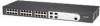
® Baseline Switch 2916-SFP Plus and the Baseline Switch 2924-SFP Plus and how they can be used in your network. It covers summaries of hardware and software features and also the following topics: ■ About the Switch 2916 and 2924 ■ Front Panel Detail ■ LED Status Indicators ■ System Specifications - 3Com 3CBLSG24 | User Guide - Page 12
Switch 2916 and 2924 includes the following models: ■ Baseline Switch 2916-SFP Plus 16-Port ■ Baseline Switch 2924-SFP Plus 24-Port The Switch 2916 mirroring Summary of Table 1 summarizes the hardware features supported by the Switch 2916 Hardware Features and 2924. Table 1 Hardware Features - 3Com 3CBLSG24 | User Guide - Page 13
Ports Supports fiber Gigabit Ethernet long-wave (LX), and fiber Gigabit Ethernet short-wave (SX) transceivers in any combination. Mounting 19-inch rack or standalone mounting Front Panel Detail Figure 1 shows the front panel of the Switch 2916-SFP Plus 16-Port unit. Figure 1 Switch 2916 SFP 16 - 3Com 3CBLSG24 | User Guide - Page 14
STARTED LED Status Indicators The 2916-SFP Plus 16-Port and 24-Port Ethernet switches provide LED indicators on the front panel for your convenience to monitor the switch. Table 2 describes the meanings of the LEDs. Table 2 Description on the LEDs of the Switch 2916 and 2924 LED Power Label - 3Com 3CBLSG24 | User Guide - Page 15
of the Switch 2916 and 2924 series switches Specification Physical dimensions (H×W×D) Weight Console port Gigabit Ethernet ports on the front panel AC Input voltage Power consumption (full load) Operating temperature Relative humidity Switch 2916-SFP Plus 16-Port 3CBLSG16 Switch 2924-SFP Plus 24 - 3Com 3CBLSG24 | User Guide - Page 16
ą lub usunięciem jakichkolwiek elementów z product lub przeprowadzeniem prac konserwacyjnych należy zapoznać się z informacjami o bezpieczeństwie zawartymi w 3Com Switch Family Safety and Regulatory Information. CAUTION: Opening the switch or tampering with the warranty sticker can void your - 3Com 3CBLSG24 | User Guide - Page 17
Interface through the Console port for basic operations of the switch including setting and viewing the IP address, configuring user accounts, upgrading switch firmware, and more. Refer to "3Com CLI Reference Guide" on page 195. Web Interface Each switch has an internal set of web pages that allow - 3Com 3CBLSG24 | User Guide - Page 18
when it is in its default state. The whole setup process is summarized in Figure 5. Detailed procedural steps are contained in the sections that follow. In brief, you need to: ■ Configure IP information manually for your switch or view the automatically configured IP information ■ Prepare for your - 3Com 3CBLSG24 | User Guide - Page 19
is automatically configured using DHCP See page 20 The switch uses its default IP information See page 20 Initial IP Information Setup Do you want to manually Yes configure the IP information? No How do you want to connect to the Switch? How do you want to view the automatically configured - 3Com 3CBLSG24 | User Guide - Page 20
automatically using DHCP, or manually using values you assign. Automatic IP Configuration using DHCP By default the switch tries to configure its IP Information without requesting user intervention. It tries to obtain an IP address from a DHCP server on the network. Default IP Address If no DHCP - 3Com 3CBLSG24 | User Guide - Page 21
Line Interface (CLI) You can access the switch through the Console port to manually set the IP address, or to view the IP address that was assigned automatically (for example, by a DHCP server). For more information about the CLI, refer to "3Com CLI Reference Guide" on page 195. Connecting to the - 3Com 3CBLSG24 | User Guide - Page 22
Refer to the documentation that accompanies the terminal emulation software for more information. 3 Power up the switch. The Power on Self Test (POST) will be performed. The Switch 2916 and 2924 takes approximately one minute to boot. Manually set the IP Address using the Console Port You are now - 3Com 3CBLSG24 | User Guide - Page 23
setup of your switch is now complete and the switch is ready for you to set up your chosen management method. See "Methods of Managing a Switch" on page 17. Viewing IP soon as the switch detects a connection to its console port. 3 At the login prompt, enter admin as your user name and press Return - 3Com 3CBLSG24 | User Guide - Page 24
a Switch" on page 17. For more information about the CLI, refer to "3Com CLI Reference Guide" on page 195. If you do not intend to use the command line interface using the console port to manage the switch, you can logout, disconnect the serial cable and close the terminal emulator software. - 3Com 3CBLSG24 | User Guide - Page 25
already set up the switch with IP information as described in "Methods of Managing a Switch" on page 17. ■ Ensure that the switch is connected to the a browser by default. You will only need to enable them if you have changed your browser settings. The switch's Web interface supports both secure ( - 3Com 3CBLSG24 | User Guide - Page 26
to address networks of all sizes and complexity. See "3Com Network Management" on page 181. Be sure the management workstation is connected to the switch using a port in VLAN 1 (the Default VLAN). By default, all ports on the switch are in VLAN 1. To display and configure SNMP management - 3Com 3CBLSG24 | User Guide - Page 27
from the Command Line Interface (CLI). Note: You can also upgrade the software using the switch Web user interface. See "Upgrade the Firmware Image" page 165. Bootcode can only be upgraded using the CLI. 1 To download the runtime application file, enter: upgrade aaa.aaa.aaa.aaa rrr runtime where - 3Com 3CBLSG24 | User Guide - Page 28
. A unique password is required of each user. Two access levels exist on the 3Com Web Interface: ■ Management access level - Provides the user with read/write access. There is always one management level user configured for the switch. The factory default is be username: admin with no Password - 3Com 3CBLSG24 | User Guide - Page 29
the 3Com user interface: 1 Open an Internet browser. 2 Enter the device IP address in the address bar and press Enter. The Enter Network Password Page opens: Figure 7 Enter Network Password Page 3 Enter your user name and password. The device default factory settings is configured with a User Name - 3Com 3CBLSG24 | User Guide - Page 30
30 CHAPTER 2: USING THE 3COM WEB INTERFACE Figure 8 3Com Web Interface Home Page Understanding the 3Com Web Interface The 3Com Web Interface Home Page contains the following views: ■ Tab View - Provides the device summary configuration located at the top of the home page. ■ Tree View - - 3Com 3CBLSG24 | User Guide - Page 31
3Com Web Interface 31 Figure 9 Web Interface Components The following table lists the user all the components under a specific feature. Provides access to user interface buttons, including both management buttons and task icons. ■ Using the Web Interface Management Buttons - Provides instructions - 3Com 3CBLSG24 | User Guide - Page 32
3Com Web Interface Home Page contains a graphical panel Representation representation of the device that appears within the Device View Tab. To access the Device Representation: 1 Click Device Summary > Device View. Figure 10 Device Representation 2 By selecting a specific 3Com 8 3Com Web Interface - 3Com 3CBLSG24 | User Guide - Page 33
Using Screen and Table Options 33 Using Screen and Table Options 3Com contains screens and tables for configuring devices. This section contains the following topics: ■ Viewing Configuration Information ■ Adding Configuration Information ■ Modifying Configuration Information ■ Removing - 3Com 3CBLSG24 | User Guide - Page 34
2: USING THE 3COM WEB INTERFACE Adding Configuration Information User-defined information can be added to specific 3Com Web Interface pages, by opening the IP Setup Page. For example, to configure IP Setup: 1 Click Administration > IP Setup. The IP Setup Page opens: Figure 12 IP Setup Page 2 Enter - 3Com 3CBLSG24 | User Guide - Page 35
Using Screen and Table Options 35 Modifying Configuration Information 1 Click Administration > System Access > Modify. The System Access Modify Page opens: Figure 13 System Access Modify Page 2 Modify the fields. 3 Click Apply. The access fields are modified. - 3Com 3CBLSG24 | User Guide - Page 36
36 CHAPTER 2: USING THE 3COM WEB INTERFACE Removing Configuration Information 1 Click Administration > System Access > Remove. The System Access Remove Page opens: Figure 14 System Access Remove Page 2 Select the user account to be deleted. 3 Click Remove. The user account is deleted, and the device - 3Com 3CBLSG24 | User Guide - Page 37
Saving the Configuration 37 Saving the Configuration Configuration changes are only saved to the device once the user saves the changes to the flash memory. The Save Configuration tab allows the latest configuration to be saved to the flash memory. To save the - 3Com 3CBLSG24 | User Guide - Page 38
38 CHAPTER 2: USING THE 3COM WEB INTERFACE Resetting the Device The Reset Page enables resetting the device from a remote location. To prevent the current configuration from being lost, use the Save Configuration Page to save all user-defined changes to the flash memory before resetting the device - 3Com 3CBLSG24 | User Guide - Page 39
- Resets the device with the factory default settings, but maintains the current IP Address, subnet mask, and default gateway address. ■ Initialize with Default IP Address - Resets the device with the factory default settings, including the factory default IP Address. 2 Click the Initialize button - 3Com 3CBLSG24 | User Guide - Page 40
40 CHAPTER 2: USING THE 3COM WEB INTERFACE Logging Off the Device To log off the device: 1 Click Logout. The Logout Page opens. 2 The following message appears: 3 Click OK. The 3Com Web Interface Home Page closes. - 3Com 3CBLSG24 | User Guide - Page 41
Page displays general information, including the system name, location, and contact, the system MAC address, System Object ID, System Up Time, and software, boot, and hardware versions. To view the Device Summary Settings: 1 Click Device Summary. The Device Summary Page opens: Figure 19 Device - 3Com 3CBLSG24 | User Guide - Page 42
number and name ■ System Name - Defines the user-defined device name. The field range is 0-160 number. ■ Product 3C Number - Displays the 3Com device 3C number. ■ System Object ID 22 minutes and 15 seconds. ■ Software Version - Displays the installed software version number. ■ Boot Version - - 3Com 3CBLSG24 | User Guide - Page 43
on 10/100/1000M port. Maximum speed 10/100/1000M RJ45 or RJ45 SFP. Indicates that a link was detected. SX/LX SFP. Indicates that a link was detected. Port has been set to inactive by User or Protocol. Port has been selected by user. Port or Transceiver has failed POST or Transceivers not recognized. - 3Com 3CBLSG24 | User Guide - Page 44
4 MANAGING DEVICE SECURITY The Management Security section provides information for configuring system access, defining RADIUS authentication, port-based authentication and defining access control lists. This section includes the following topics: ■ Configuring System Access ■ Defining RADIUS - 3Com 3CBLSG24 | User Guide - Page 45
. A unique password is required of each user. Two access levels exist on the 3Com Web Interface: ■ Management access level - Provides the user with read/write access. There is always one management level user configured for the switch. The factory default is be user name: admin with no Password - 3Com 3CBLSG24 | User Guide - Page 46
predefined field value is: ■ Admin - Displays the predefined Administrative user name. ■ Access Level - Displays the user access level. The lowest user access level is Monitor and the highest is Management. ■ Management - Provides the user with read and write access rights. ■ Monitor - Provides the - 3Com 3CBLSG24 | User Guide - Page 47
Administration > System Access > Setup. The System Access Setup Page opens: Figure 22 System Access Setup Page The System Access Setup Page contains the following fields: ■ User Name - Defines the user name. ■ Access Level - Defines the user access level. The lowest user access level is Monitor and - 3Com 3CBLSG24 | User Guide - Page 48
Modify Page opens: Figure 23 System Access Modify Page The System Access Modify Page contains the following fields: ■ User Name - Displays the user name. ■ Access Level - Displays the user access level. The lowest user access level is Monitoring and the highest is Management. ■ Management - Provides - 3Com 3CBLSG24 | User Guide - Page 49
System Access Remove Page contains the following fields: ■ Remove User(s) - Select user(s) from the list below to be removed. ■ User Name - Displays the user name. ■ Access Level - Displays the user access level. The lowest user access level is Monitoring and the highest is Management. ■ Management - 3Com 3CBLSG24 | User Guide - Page 50
DEVICE SECURITY Defining RADIUS Clients Remote Authorization Dial-In User Service (RADIUS) servers provide additional security for networks. RADIUS servers provide a centralized authentication method for 802.1X. The default parameters are user-defined, and are applied to newly defined RADIUS - 3Com 3CBLSG24 | User Guide - Page 51
before retrying the query, or switching to the next server. Possible field values are 1-30. The default value is 3. ■ Dead Time - Defines the default amount of time (in minutes) that a RADIUS server is bypassed for service requests. The range is 0-2000. The default value is 0. ■ Key String - Defines - 3Com 3CBLSG24 | User Guide - Page 52
-based authentication authenticates users on a per-port basis via an external server. Only authenticated and approved system users can transmit and , and indicates whether the supplicant is authorized to access system services. Port-based authentication creates two access states: ■ Controlled Access - 3Com 3CBLSG24 | User Guide - Page 53
26 802.1X Summary Page The 802.1X Summary Page contains the following fields: ■ Port - Displays a list of interfaces. ■ User Name - Displays the supplicant user name. ■ Admin Port Control - Displays the admin port authorization state. ■ ForceUnauthorized - Indicates that either the port control is - 3Com 3CBLSG24 | User Guide - Page 54
the periodic reauthentication on the port. This is the default. ■ Reauthentication Period - Displays the time span (in Setup Page contains information for configuring 802.1X Authentication global settings on the device and defining specific 802.1X setting for each port individually. Monitor users - 3Com 3CBLSG24 | User Guide - Page 55
1 Click Security > 802.1X > Setup. The 802.1X Setup Page opens: Figure 27 802.1X Setup Page The 802.1X Setup Page contains the following fields: 802. - Disables port-based authentication on the device. This is the default value. ■ Authentication Method - Specifies the authentication method used for - 3Com 3CBLSG24 | User Guide - Page 56
authentication, but grant Internet access to unauthorized users. ■ Guest VLAN ID - Specifies the . The device cannot provide authentication services to the client through the interface Guest VLAN on the port. This is the default. ■ Periodic Reauthentication - Enables periodic reauthentication on - 3Com 3CBLSG24 | User Guide - Page 57
ACL) allow network managers to define classification actions and rules for specific ingress ports. Packets entering an ingress port, with an active ACL ■ Removing MAC Based ACLs ■ Viewing IP Based ACLs ■ Defining IP Based ACLs ■ Modifying IP Based ACLs ■ Removing IP Based ACLs ■ Viewing ACL Binding ■ - 3Com 3CBLSG24 | User Guide - Page 58
58 CHAPTER 4: MANAGING DEVICE SECURITY Viewing MAC Based The MAC Based ACL Summary Page displays information regarding MAC ACLs Based ACLs configured on the device. Ports are reactivated from the Interface Configuration Page. To view MAC Based ACLs: 1 Click Device > ACL > MAC Based ACL > Summary. - 3Com 3CBLSG24 | User Guide - Page 59
and define rules for MAC-based Access Control Lists. Monitor users have no access to this page. 1 Click Device > ACL > MAC Based ACL > Setup. The MAC Based ACL Setup Page opens: Figure 29 MAC Based ACL Setup Page The MAC Based ACL Setup Page contains the following fields: ■ Selection ACL - Lists - 3Com 3CBLSG24 | User Guide - Page 60
60 CHAPTER 4: MANAGING DEVICE SECURITY Add Rules to ACL ■ Priority - Indicates the ACE priority, which determines which ACE is matched to a packet on a first-match basis. The possible field values are 1-2147483647. ■ Source MAC Address - Matches the source MAC address to which packets are addressed - 3Com 3CBLSG24 | User Guide - Page 61
Page. 2 Define the fields. 3 Click Apply. The Rule Setup settings are configured, and the device is updated. Modifying MAC The MAC Based ACL Modify Page allows the network administrator to Based ACLs modify MAC Based ACLs settings. Monitor users have no access to this page. 1 Click Device > ACL - 3Com 3CBLSG24 | User Guide - Page 62
62 CHAPTER 4: MANAGING DEVICE SECURITY Modify ■ Priority - Indicates the rule priority, which determines which rule is matched to a packet on a firstmatch basis. ■ Source MAC Address - Matches the source MAC address to which packets are addressed to the ACE. ■ Source Mask - Indicates the source MAC - 3Com 3CBLSG24 | User Guide - Page 63
which the packet was addressed. Ports are reactivated from the Port Administration Setup Page. 2 Define the fields. 3 Click Apply. The MAC based MAC Based The MAC Based ACL Remove Page allows the user to remove MAC Based ACLs ACLs. Monitor users have no access to this page. To remove MAC Based - 3Com 3CBLSG24 | User Guide - Page 64
. The possible field values are 1 to 4093. ■ CoS - Classifies Class of Service of the packet. ■ CoS Mask - Defines the wildcard bits to be applied to to which the packet was addressed. Ports are reactivated from the Port Administration Setup Page. 2 Select the ACL Name to be deleted. 3 Select the ACL - 3Com 3CBLSG24 | User Guide - Page 65
Access Control Lists 65 Viewing IP Based The IP Based ACL Summary Page displays information regarding IP Based ACLs ACLs configured on the device. To view IP Based ACLs: 1 Click Device > ACL > IP Based ACL > Summary. The IP Based ACL Summary Page opens: Figure 32 IP Based ACL Summary Page The - 3Com 3CBLSG24 | User Guide - Page 66
packet was addressed. Ports are reactivated from the Port Administration Setup Page. Defining IP Based ACLs Access Control Lists (ACL) allow network managers to define classification actions and rules for specific ingress ports. Your switch supports up to 256 ACLs. Packets entering an ingress port - 3Com 3CBLSG24 | User Guide - Page 67
Lists: 1 Click Device > ACL > IP Based ACL > Setup. The IP Based ACL Setup Page opens: Figure 33 IP Based ACL Setup Page The IP Based ACL Setup Page contains the following fields: ■ Selection ACL - Selects the ACL to be bound. ■ Create ACL - Defines a new user-defined IP based ACL. Add Rules to ACL - 3Com 3CBLSG24 | User Guide - Page 68
used for matched packets. Enabled only when TCP or UDP are selected in the Protocol list. The field value is either user defined or Any. If Any is selected, the IP based ACL is applied to any destination port. ■ TCP Flags - If checked, enables configuration of TCP flags matched to the packet - 3Com 3CBLSG24 | User Guide - Page 69
to the ACE, according to a wildcard mask. The field value is either user defined or Any. If Any is selected, accepts any source IP address and disables wildcard mask filtering. ■ Wild Card Mask - Defines the source IP address wildcard mask. Wildcard masks specify which bits are used and which bits - 3Com 3CBLSG24 | User Guide - Page 70
Name drop-down list. 3 Define the rule setup fields. 4 Click Apply. The ACL rule setup is enabled, and the device is updated. Modifying IP Based ACLs The IP Based ACL Modify Page allows the network administrator to modify IP Based ACLs settings. Monitor users have no access to this page. Figure - 3Com 3CBLSG24 | User Guide - Page 71
Defining Access Control Lists 71 The IP Based ACL Modify Page contains the following fields: ■ on which ACE can be based. ■ Protocol ID - Adds user-defined protocols by which packets are matched to the ACE. Each protocol has a specific protocol number which is unique. The possible field range is - 3Com 3CBLSG24 | User Guide - Page 72
of 255.255.255.255 indicates that no bit is important. A mask of 0.0.0.0 indicates that all the bits are important. For example, if the source IP address is 149.36.184.198 and the wildcard mask is 255.255.255.00, the first three bytes of the - 3Com 3CBLSG24 | User Guide - Page 73
. Ports are reactivated from the Port Administration Setup Page. Removing IP Based The IP Based ACL Remove Page allows the user to remove IP Based ACLs. ACLs Monitor users have no access to this page. 1 Click Device > ACL > IP Based ACL > Remove. The IP Based ACL Remove Page opens: Figure 35 - 3Com 3CBLSG24 | User Guide - Page 74
■ DSCP - Matches the packet DSCP value to the ACL. Either the DSCP value or the IP Precedence value is used to match packets to ACLs. ■ IP - Prec. - Indicates matching ip-precedence with the packet IP precedence value. ■ Action - Indicates the ACL forwarding action. In addition, the port can be shut - 3Com 3CBLSG24 | User Guide - Page 75
which the packet was addressed. Ports are reactivated from the Port Administration Setup Page. 2 Select an ACL to be removed. 3 Click Apply. The device is updated. Viewing ACL Binding The ACL Binding Summary Page displays the user-defined ACLs mapped to the interfaces. To view ACL Binding: 1 Click - 3Com 3CBLSG24 | User Guide - Page 76
76 CHAPTER 4: MANAGING DEVICE SECURITY Configuring ACL The ACL Binding Setup Page allows the network administrator to bind Binding specific ports to MAC or IP Based ACLs. The monitor user has no access to this page. To define ACL Binding: 1 Click Device > ACL > ACL Binding > Summary. The ACL Binding - 3Com 3CBLSG24 | User Guide - Page 77
Defining Access Control Lists 77 Removing ACL The ACL Binding Remove Page allows the network administrator to Binding remove user-defined ACLs from a selected interface. Monitor users have no access to this page. To remove ACL Binding: 1 Click Device > ACL > ACL Binding > Remove. The ACL Binding - 3Com 3CBLSG24 | User Guide - Page 78
each port, and discards the frames when the rate exceeds a user-defined rate. Packet threshold is ignored if Broadcast Storm Control is Disabled. Monitor users have no access to this page. 1 Click Device > Broadcast Storm > Setup. The Broadcast Storm Setup Page opens: Figure 39 Broadcast Storm - 3Com 3CBLSG24 | User Guide - Page 79
Enabling Broadcast Storm 79 The Broadcast Storm Setup Page contains the following fields: ■ Broadcast Storm Control - at which unknown packets are forwarded. The range is 3,500-1,000,000. The default value is 3500. 2 Define the relevant fields. 3 Click Apply. Broadcast Storm is defined, and - 3Com 3CBLSG24 | User Guide - Page 80
■ Configuring System Time Viewing System Description The Device View Page displays parameters for configuring general device information, including the system name, MAC Address, software and hardware versions, and more. 1 Click Device Summary. The Device View Page opens. Figure 40 Device View Page - 3Com 3CBLSG24 | User Guide - Page 81
user-editable. ■ System Name - Displays the user Displays the 3Com device software version number. ■ Boot Version - Displays the current boot version running on the device. ■ Hardware Version - Displays the current hardware version of the device. ■ Poll Now - This button immediately polls the switch - 3Com 3CBLSG24 | User Guide - Page 82
Page The System Name Page includes the following fields: ■ System Name - Defines the user-defined device name. The field range is 0-100 characters. ■ System Location - Defines changes will be lost when the switch is rebooted. To save the configuration, refer to "Saving the Configuration" on page 37. - 3Com 3CBLSG24 | User Guide - Page 83
on the device. Monitor users have limited permissions on this page. Country specific times need to be added manually. To configure the System Time: 1 Click Administration > System Time. The System Time Setup Page opens: Figure 42 System Time Setup Page The System Time Setup Page contains the - 3Com 3CBLSG24 | User Guide - Page 84
First Sunday of November ■ European - The device switches to DST at 1:00 am on the last Sunday standard. ■ Other - The DST definitions are user-defined and can be customized to your location. If amount of time adjusted for DST (in minutes). The default time is 60 minutes. ■ From - Indicates the non - 3Com 3CBLSG24 | User Guide - Page 85
6 CONFIGURING PORTS Viewing Port Settings This section contains information for configuring Port Settings, and includes the following sections: ■ Viewing Port Settings ■ Defining Port Settings ■ Viewing Port Details The Port Administration Summary Page permits the network manager to view the - 3Com 3CBLSG24 | User Guide - Page 86
86 CHAPTER 6: CONFIGURING PORTS To view Port Settings: 1 Click Port > Administration > Summary. The Port Administration Summary Page opens: Figure 43 Port Administration Summary Page The Port Administration Summary Page contains the following fields: ■ Port - Indicates the selected port number. ■ - 3Com 3CBLSG24 | User Guide - Page 87
cannot be configured on LAGs. The possible field values are: ■ Full - The interface supports transmission between the device and its link partner in both directions simultaneously. ■ Half - The interface supports transmission between the device and the client in only one direction at a time. ■ Flow - 3Com 3CBLSG24 | User Guide - Page 88
to configure port parameters for specific ports. Monitor users have no access to this page. To configure Port Settings: 1 Click Port > Administration > Setup. The Port Administration Setup Page opens: Figure 44 Port Administration Setup Page The Port Administration Setup Page contains the following - 3Com 3CBLSG24 | User Guide - Page 89
field values are: ■ Auto - Use to automatically configure the port. ■ Full - The interface supports transmission between the device and its link partner in both directions simultaneously. ■ Half - The interface supports transmission between the device and the client in only one direction at a time - 3Com 3CBLSG24 | User Guide - Page 90
90 CHAPTER 6: CONFIGURING PORTS Viewing Port Details The Port Detail Page displays current port parameters for specific ports. Monitor users have no access to this page. To view Port Details: 1 Click Port > Administration > Detail. The Port Detail Page opens: Figure 45 Port Detail Page The - 3Com 3CBLSG24 | User Guide - Page 91
field values are: ■ Auto - Use to automatically configure the port. ■ Full - The interface supports transmission between the device and its link partner in both directions simultaneously. ■ Half - The interface supports transmission between the device and the client in only one direction at a time - 3Com 3CBLSG24 | User Guide - Page 92
and flow control modes. ■ All ports in the LAG have the same priority. ■ All ports in the LAG have the same transceiver type. ■ The device supports up to eight LAGs, and eight ports in each LAG. ■ Ports added to a LAG lose their individual port configuration. When ports are removed from the - 3Com 3CBLSG24 | User Guide - Page 93
linking a group of ports together to form a single LAG. Aggregating ports multiplies the bandwidth between the devices, increases port flexibility, and provides link redundancy. Monitor users have no access to this page. - 3Com 3CBLSG24 | User Guide - Page 94
94 CHAPTER 7: AGGREGATING PORTS 1 Click Ports > Link Aggregation > Create. The Link Aggregation Create Page opens: Figure 47 Link Aggregation Create Page The Link Aggregation Create Page includes the following fields: ■ Enter aggregation Group ID - Displays the group ID. The range is 1-8 groups. ■ - 3Com 3CBLSG24 | User Guide - Page 95
together to form a single LAG. Aggregating ports multiplies the bandwidth between the devices, increases port flexibility, and provides link redundancy. Monitor users have no access to this page. To modify Link Aggregation: 1 Click Ports > Link Aggregation > Modify. The Link Aggregation Modify Page - 3Com 3CBLSG24 | User Guide - Page 96
is updated. Removing Link Aggregation The Link Aggregation Remove Page allows the network manager to remove group IDs containing member ports. Monitor users have no access to this page. To remove Link Aggregation: 1 Click Ports > Link Aggregation > Remove. The Link Aggregation Remove Page opens - 3Com 3CBLSG24 | User Guide - Page 97
is updated. LAG ports can contain different media types if the ports are operating at the same speed. Aggregated links can be set up manually or automatically established by enabling LACP on the relevant links. Aggregate ports can be linked into link-aggregation port-groups. The LACP Summary Page - 3Com 3CBLSG24 | User Guide - Page 98
Modifying LACP LAG ports can contain different media types if the ports are operating at the same speed. Aggregated links can be set up manually or automatically established by enabling LACP on the relevant links. Aggregate ports can be linked into link-aggregation port-groups. The LACP Modify Page - 3Com 3CBLSG24 | User Guide - Page 99
99 The LACP Modify Page contains the following fields: ■ LACP System Priority - Specifies system priority value. The field range is 1-65535. The field default is 1 ■ Select Port - Displays the port number to which timeout and priority values are assigned. ■ LACP Port Priority - Displays the LACP - 3Com 3CBLSG24 | User Guide - Page 100
(LAN) which combine user stations and network devices into the management VLAN. You can only manage the switch through a port that is an untagged member software-based and not defined by physical attributes. VLANs function at Layer 2. Since VLANs isolate traffic within the VLAN, a Layer 3 router - 3Com 3CBLSG24 | User Guide - Page 101
remains untagged in VLAN1. A port can only be an untagged member of one VLAN. By default it is untagged member of VLAN1. If its untagged membership from another VLAN is removed, it will default to untagged membership in VLAN1. There is no restriction on tagged membership. A port can be a tagged - 3Com 3CBLSG24 | User Guide - Page 102
102 CHAPTER 8: CONFIGURING VLANS Viewing VLAN Details The VLAN Detail Page provides information and global parameters on VLANS configured on the system. 1 Click Device > VLAN > VLAN Detail. The VLAN Detail Page opens: Figure 52 VLAN Detail Page The VLAN Detail Page contains the following - 3Com 3CBLSG24 | User Guide - Page 103
Viewing VLAN Port Details 103 Viewing VLAN Port Details The VLAN Port Detail Page provides displays VLAN configured ports. To view VLAN Port details: 1 Click Device > VLAN > Port Detail. The VLAN Port Detail Page opens: Figure 53 VLAN Port Detail Page The VLAN Port Detail Page contains the - 3Com 3CBLSG24 | User Guide - Page 104
Page allows the network administrator to create user-defined VLANs. The monitor users have no access to this page. To create VLANs: 1 Click Device > VLAN > Setup. The VLAN Setup Page opens: Figure 54 VLAN Setup Page The VLAN Setup Page contains the following fields: Create ■ VLAN IDs - Creates - 3Com 3CBLSG24 | User Guide - Page 105
the device is updated. Modifying VLAN Settings The Modify VLAN Page allows the network manager to rename VLANs and change VLAN membership. The monitor users have no access to this page. To edit VLAN Settings: 1 Click Device > VLAN > Modify VLAN. The Modify VLAN Page opens: Figure 55 Modify VLAN - 3Com 3CBLSG24 | User Guide - Page 106
the interface is not a member of the VLAN. ■ Not Available for Selection - Indicates the interface is not available for selection. ■ Select All - Allows the user to select all ports to be added to the VLAN. ■ Select None - Removes the ports selected. To rename VLANs: 1 Select a VLAN from the list - 3Com 3CBLSG24 | User Guide - Page 107
Modifying Port VLAN Settings 107 Modifying Port VLAN Settings The Modify VLAN Port Page allows the network manager to modify port VLAN settings. The monitor users have no access to this page. 1 Click Device > VLAN > Modify Port. The Modify VLAN Port Page opens: Figure 56 Modify VLAN Port Page The - 3Com 3CBLSG24 | User Guide - Page 108
. The VLANs are configured, and the device is updated. Removing VLANs The VLAN Remove Page allows the network administrator to remove VLANs. The monitor users have no access to this page. 1 Click Device > VLAN > Remove. The VLAN Remove Page opens: Figure 57 VLAN Remove Page The VLAN Remove Page - 3Com 3CBLSG24 | User Guide - Page 109
assigning an IP address. The default gateway is erased when the Default IP address is modified. Packets are forwarded to the default gateway when sent to a remote network. The monitor user has no access to this page. 1 Click Administration > IP Setup. The IP Setup Page opens: Figure 58 IP Setup Page - 3Com 3CBLSG24 | User Guide - Page 110
by the user. ■ DHCP - Indicates that the IP Interface is dynamically created. ■ IP Address - Displays the currently configured IP address. ■ Subnet Mask - Displays the currently configured subnet mask. ■ Default Gateway - Displays the currently configured default gateway. 2 Select Manual or DHCP - 3Com 3CBLSG24 | User Guide - Page 111
is associated with the MAC Address. ■ MAC Address - Displays the station MAC address, which is associated in the ARP table with the IP address. ■ Status - Displays the ARP table entry type. Possible field values are: ■ Dynamic - Indicates the ARP entry is learned dynamically. ■ Static - Indicates - 3Com 3CBLSG24 | User Guide - Page 112
IP AND MAC ADDRESS INFORMATION Defining ARP Settings The ARP Settings Setup Page allows network managers to define ARP parameters for specific interfaces. The monitor users have no access to this page. To configure ARP entries: 1 Click Administration > ARP Settings > Setup. The ARP Settings Setup - 3Com 3CBLSG24 | User Guide - Page 113
the ARP Table. The monitor user has no access to this page. To remove ARP entries: 1 Click Administration > IP Addressing > ARP Settings > entries. ■ Static - Clears only static ARP entries. ■ Remove - Removes a specific ARP entry. The possible field values are: ■ Checked - Removes the selected ARP - 3Com 3CBLSG24 | User Guide - Page 114
the station MAC address, which is associated in the ARP table with the IP address. ■ Status - Displays the ARP table entry type. Possible field values flooded to all ports of the relevant VLAN. Static addresses are manually configured. In order to prevent the bridging table from overflowing, dynamic - 3Com 3CBLSG24 | User Guide - Page 115
values are: ■ All - Displays all MAC Addresses. ■ Static - Displays the MAC Addresses that were entered by a user. ■ Dynamic - Displays the MAC Addresses that were detected by the switch. ■ MAC Address - Displays the current MAC addresses listed in the MAC address table, filtered by the selected - 3Com 3CBLSG24 | User Guide - Page 116
116 CHAPTER 9: CONFIGURING IP AND MAC ADDRESS INFORMATION ■ Config Dynamic - Indicates the MAC the source is detected. The default value is 300 seconds. Viewing Port The Port Summary Page allows the user to view the MAC addresses Summary Settings assigned to specific ports. 1 Click Monitoring - 3Com 3CBLSG24 | User Guide - Page 117
is timed out if no traffic from the source is detected. The default value is 300 seconds. Adding Entries into The Address Table Add Page manager to assign MAC Address Tables addresses to ports with VLANs. The monitor users have no access to this page. To add Address Tables: 1 Click Monitoring - 3Com 3CBLSG24 | User Guide - Page 118
IP AND MAC ADDRESS INFORMATION The Address Table Add Page contains the following fields: ■ VLAN ID - Assigns a VLAN ID to the user-defined MAC Address. ■ MAC Address - Defines a MAC Address to be assigned to the specific the source is detected. The default value is 300 seconds. 2 Define the fields - 3Com 3CBLSG24 | User Guide - Page 119
source is detected. The default value is 300 seconds. The monitor users have no access to this page. To define the Aging Time: 1 Click Monitoring > Address Tables > Setup. The Address Table Setup Page opens: Figure 65 Address Table Setup Page The Address Table Setup Page contains the following - 3Com 3CBLSG24 | User Guide - Page 120
120 CHAPTER 9: CONFIGURING IP AND MAC ADDRESS INFORMATION Removing Address The Port Remove Page allows the network manager to remove ports from Table Ports the address tables. The monitor users have no access to this page. To remove ports: 1 Click Monitoring > Address Tables > Port Remove. The Port - 3Com 3CBLSG24 | User Guide - Page 121
Address before it is timed out if no traffic from the source is detected. The default value is 300 seconds. 2 Select the port(s) to remove. 3 Click Remove. to remove Tables current MAC addresses from the Address Table. The monitor users have no access to this page. To remove Address Tables: 1 Click - 3Com 3CBLSG24 | User Guide - Page 122
122 CHAPTER 9: CONFIGURING IP AND MAC ADDRESS INFORMATION ■ Config Static - Indicates the MAC address is Dynamic MAC Address before it is timed out if no traffic from the source is detected. The default value is 300 seconds. 2 Select the MAC addresses to remove. 3 Click Remove. The selected MAC - 3Com 3CBLSG24 | User Guide - Page 123
ports want to join which Multicast groups. ■ Which ports have Multicast routers generating IGMP queries. ■ Which routing protocols are forwarding packets and Multicast traffic. Ports requesting to join a specific Multicast group issue an IGMP report, specifying that Multicast group is accepting - 3Com 3CBLSG24 | User Guide - Page 124
users have read-only access to this page. 1 Click Device > IGMP Snooping > Setup. The IGMP Snooping Setup Page opens: Figure 68 IGMP Snooping Setup Page The IGMP Snooping Setup ■ Disable - Disables IGMP Snooping on the VLAN. This is the default value. ■ Enable - Enables IGMP Snooping on the VLAN. - 3Com 3CBLSG24 | User Guide - Page 125
Defining IGMP Snooping 125 2 Select Enable IGMP Snooping. 3 Define the fields. 4 Click Apply. IGMP Snooping is enabled, and the device is updated. - 3Com 3CBLSG24 | User Guide - Page 126
Spanning Tree Protocol (RSTP) detects and uses network topologies that allow a faster STP convergence without creating forwarding loops. The device supports the following STP versions: ■ Classic STP - Provides a single path between end stations, avoiding and eliminating loops. ■ Rapid STP - Detects - 3Com 3CBLSG24 | User Guide - Page 127
the port link is up. Fast Link optimizes the STP protocol convergence. STP convergence takes 30 seconds and is not dependent on the number of switches in the network. - 3Com 3CBLSG24 | User Guide - Page 128
128 CHAPTER 11: CONFIGURING SPANNING TREE ■ Root Guard - Restricts the interface from acting as the root port of the switch. The possible field values are: ■ Enable - Indicates Root Guard is enabled on the port ■ Disable - Indicates Root Guard is disabled on the port. ■ Port State - - 3Com 3CBLSG24 | User Guide - Page 129
Viewing Spanning Tree 129 ■ Path Cost - Indicates the port contribution to the root path cost. The path cost is adjusted to a higher or lower value, and is used to forward traffic when a path is re-routed. ■ Priority - Priority value of the port. The priority value influences the port choice when a - 3Com 3CBLSG24 | User Guide - Page 130
settings to specific interfaces using the Spanning Tree Setup Page. The monitor user has no access to this page. To configure Spanning Tree Setup: 1 Click Device > Spanning Tree > Setup. The Spanning Tree Setup Page opens: Figure 70 Spanning Tree Setup Page The Spanning Tree Setup Page contains - 3Com 3CBLSG24 | User Guide - Page 131
through 200,000,000 range for port path cost. The default path cost assigned to an interface varies according to the selected method (Hello Time, Max Age, or Forward Delay). Bridge Setting ■ Priority - Specifies the bridge priority value. When switches or bridges are running STP, each is assigned - 3Com 3CBLSG24 | User Guide - Page 132
offers the lowest cost path from this bridge to the Root Bridge. This field is significant when the bridge is not the Root Bridge. The default is zero. ■ Root Path Cost - Specifies the cost of the path from this bridge to the Root Bridge. ■ Topology Changes Counts - Specifies the total amount - 3Com 3CBLSG24 | User Guide - Page 133
Modifying Spanning Tree TheSpanning Tree Modify Page contains information for modifying Spanning Tree parameters. Monitor users have no access to this page. To modify Spanning Tree: 1 Click Device > seconds and is not dependent on the number of switches in the network. The possible field values are: - 3Com 3CBLSG24 | User Guide - Page 134
Restricts the interface from acting as the root port of the switch. The possible field values are: ■ Enable - Indicates Default Path Cost - Indicates if Default Path Cost is enabled. The possible field values are: ■ Enable - Enables the default path cost on the port. ■ Disable - Disables the default - 3Com 3CBLSG24 | User Guide - Page 135
device supports the following SNMP versions: ■ SNMP version 1 ■ SNMP version 2c SNMP v1 and v2c The SNMP agents maintain a list of variables, which are used to manage the device. The variables are defined in the Management Information Base (MIB). The SNMP agent defines the MIB specification format - 3Com 3CBLSG24 | User Guide - Page 136
for SNMP v1 and SNMP v2c. Monitor users have no access to this page. To define SNMP communities: 1 Click Administration > SNMP > Communities > Setup. The SNMP Communities Setup Page opens: Figure 72 SNMP Communities Setup Page The SNMP Communities Setup Page contains the following fields: ■ SNMP - 3Com 3CBLSG24 | User Guide - Page 137
SNMP Management ■ Management Station - Displays the management station IP address for which the SNMP community is defined. ■ Open Private - Displays the pre-defined private community string name. ■ User Defined - Defines a user-defined community string name. ■ Access Mode - Defines the access rights - 3Com 3CBLSG24 | User Guide - Page 138
the selected SNMP community. ■ Unchecked - Maintains the SNMP communities. ■ Management Station - Displays the management station IP address for which the SNMP community is defined. ■ Community String - Displays the user-defined text string which authenticates the management station to the device. - 3Com 3CBLSG24 | User Guide - Page 139
is removed, and the device is updated. Defining SNMP Traps The SNMP Traps Setup Page contains information for defining filters that determine whether traps are sent to specific users, and the trap type sent. Monitor users have no access to this page. To define SNMP traps: 1 Click Administration - 3Com 3CBLSG24 | User Guide - Page 140
CONFIGURING SNMP The SNMP Traps Setup Page contains the following fields: ■ Recipients IP Address - Defines the IP address to which the traps SNMP Traps Remove Page allows the network manager to remove SNMP Traps. Monitor users have no access to this page. To remove SNMP traps: 1 Click - 3Com 3CBLSG24 | User Guide - Page 141
field values are: ■ Checked - Removes the selected recipient from the list of recipients. ■ Unchecked - Maintains the list of recipients. ■ Recipients IP - Defines the IP address to which the traps are sent. ■ Trap - Displays the trap type. The possible field values are: ■ SNMP V1 - Indicates that - 3Com 3CBLSG24 | User Guide - Page 142
QUALITY OF SERVICE Quality of Service (QoS are matched to specific values. All packets matching the user-defined specifications are classified together. the egress queues. VPT to Queue assignments are user-definable. Packets arriving untagged are assigned a default VPT value, which is set on a per- - 3Com 3CBLSG24 | User Guide - Page 143
CoS Summary Page The CoS Summary Page contains the following fields: ■ Interface - Displays the interface for which the CoS default value is defined. ■ Default CoS - Displays the default CoS value for incoming packets for which a VLAN priority tag is not defined. The possible field values are 0-7. - 3Com 3CBLSG24 | User Guide - Page 144
CONFIGURING QUALITY OF SERVICE Defining CoS The CoS Setup Page contains information for enabling QoS globally. Monitor users have no access to this page. To configure CoS Settings: 1 Click Device > QoS > CoS Setup. The CoS Setup Page opens: Figure 77 CoS Setup Page The CoS Setup Page contains the - 3Com 3CBLSG24 | User Guide - Page 145
to Queue Summary Page contains the following fields: ■ Class of Service - Specifies the CoS priority tag values, where zero is supported. The CoS to Queue Setup Page contains fields for mapping CoS values to traffic queues. Four traffic priority queues are supported user has no access to this page. - 3Com 3CBLSG24 | User Guide - Page 146
> CoS to Queue > Setup. The CoS to Queue Setup Page opens: Figure 79 CoS to Queue Setup Page The CoS to Queue Setup Page contains the following fields: ■ Restore Defaults - Restores the device factory defaults for mapping CoS values to a forwarding queue. ■ Class of Service - Specifies the CoS - 3Com 3CBLSG24 | User Guide - Page 147
: ■ DSCP - Displays the incoming packet's DSCP value. ■ Queue - Specifies the traffic forwarding queue to which the DSCP priority is mapped. Four traffic priority queues are supported. - 3Com 3CBLSG24 | User Guide - Page 148
to queue 1. The monitor user has no access to this page. To map CoS to Queues: 1 Click Device > QoS > DSCP to Queue > Setup. The DSCP to Queue Setup Page opens: Figure 81 DSCP to Queue Setup Page The DSCP to Queue Setup Page contains the following fields: ■ Restore Defaults - Restores the device - 3Com 3CBLSG24 | User Guide - Page 149
on configured interfaces. The original device QoS default settings can be reassigned to the interface in the Trust Setup Page. To enable Trust: 1 Click Device > QoS > Trust Setup. The Trust Setup Page opens: Figure 82 Trust Setup Page The Trust Setup Page contains the following fields: ■ Trust - 3Com 3CBLSG24 | User Guide - Page 150
150 CHAPTER 13: CONFIGURING QUALITY OF SERVICE Viewing Bandwidth The Bandwidth Summary Page displays bandwidth settings for a specified Settings interface. To view Bandwidth Settings: 1 Click Device > QoS > Bandwidth > Summary. The Bandwidth Summary - 3Com 3CBLSG24 | User Guide - Page 151
16,769,020 bytes per second. Defining Bandwidth Settings The Bandwidth Setup Page allows network managers to define the bandwidth settings for a . The interface shaping type is selected in the Bandwidth Setup Page. The monitor user has no access to this page. To configure Bandwidth Settings - 3Com 3CBLSG24 | User Guide - Page 152
152 CHAPTER 13: CONFIGURING QUALITY OF SERVICE The Bandwidth Setup Page contains the following fields: Ingress Rate Limit ■ Enable Ingress Rate Limit - Enables setting an Ingress Rate Limit. ■ Ingress Rate Limit - Indicates the traffic limit - 3Com 3CBLSG24 | User Guide - Page 153
network administrators enhance VoIP service by configuring ports to carry IP voice traffic from IP phones on a specific VLAN. VoIP traffic deteriorate if the IP traffic is received unevenly. The system supports one Voice VLAN. There are two operational modes for IP Phones: ■ IP phones are configured - 3Com 3CBLSG24 | User Guide - Page 154
154 CHAPTER 13: CONFIGURING QUALITY OF SERVICE Viewing Voice VLANs The Voice VLAN Summary Page - Indicates the amount of time after the last IP phone's OUI is aged out for a specific port. The port will age out after the bridge and voice aging time. The default time is one day. The field format is - 3Com 3CBLSG24 | User Guide - Page 155
dynamic ports added to the Voice VLAN in Auto mode. ■ Static Members - Displays static ports that were manually added to the Voice VLAN. Defining Voice VLAN The Voice VLAN Setup Page provides information for enabling and defining Voice VLAN globally on the device. To configure Voice VLAN Settings - 3Com 3CBLSG24 | User Guide - Page 156
SERVICE ■ Voice VLAN Aging Time - Indicates the amount of time after the last IP phone's OUI is aged out for a specific port. The port will age out after the bridge and voice aging time. The default Defining Voice VLAN The Voice VLAN Port Setup Page contains information for defining Voice Port - 3Com 3CBLSG24 | User Guide - Page 157
IP phones OUI was added manually to a port/LAG in the Voice VLAN, the user cannot add it to the Voice VLAN in Auto mode, only in Manual Disables port security on the Voice VLAN. This is the default value. ■ Select Port - Enables selecting specific ports and LAGs to which the Voice VLAN settings are - 3Com 3CBLSG24 | User Guide - Page 158
the current Voice VLAN port settings. This is the default value. ■ None - Indicates that the selected port will not be added to a Voice VLAN. ■ Manual - Adding a selected port to a Voice VLAN. ■ Auto - Indicates that if traffic with an IP Phone MAC Address is transmitted on the port, the port - 3Com 3CBLSG24 | User Guide - Page 159
three bytes of the MAC Address contain a manufacturer identifier. While the last three bytes contain a unique station ID. Using the OUI, network managers can add specific manufacturer's MAC addresses to the OUI table. Once the OUIs are added, all traffic received on the Voice VLAN ports from the - 3Com 3CBLSG24 | User Guide - Page 160
160 CHAPTER 13: CONFIGURING QUALITY OF SERVICE To view VLAN Settings: 1 Click default. ■ 00:E0:BB - Assigned to 3Com IP Phones. ■ 00:03:6B - Assigned to Cisco IP Phones. ■ 00:E0:75 - Assigned to Polycom/Veritel IP Phones. ■ 00:D0:1E - Assigned to Pingtel IP Phones. ■ 00:01:E3 - Assigned to Siemens IP - 3Com 3CBLSG24 | User Guide - Page 161
OUIs are added, all traffic received on the Voice VLAN ports from the specific IP phone with a listed OUI, is forwarded on the voice VLAN. To modify - Defines new OUIs enabled on the Voice VLAN. ■ Description - Provides a user-defined OUI description. 2 Enter an OUI in the Telephony OUI field. 3 - 3Com 3CBLSG24 | User Guide - Page 162
up switch firmware, including the following topics: ■ Backing Up System Files ■ Restoring Files ■ Upgrade the Firmware Image file to the Startup Configuration file. ■ Image files - Software upgrades are used when a new version file is downloaded. The file is checked for the right format, and - 3Com 3CBLSG24 | User Guide - Page 163
the system Files configuration to a TFTP or HTTP server. The monitor users have no access to this page. 1 To keep your currently running the HTTP server or HTTPS server. ■ TFTP Server IP Address - Specifies the TFTP Server IP Address to which the configuration files are uploaded. ■ - 3Com 3CBLSG24 | User Guide - Page 164
the TFTP or HTTP server. The monitor users have no access to this page. 1 Click Download via TFTP - Enables a download from the TFTP server. ■ Download via HTTP - Enables a download from the HTTP server or HTTPS server. Configuration Download ■ TFTP Server IP Address - Specifies the TFTP Server IP - 3Com 3CBLSG24 | User Guide - Page 165
to upgrade the switch firmware. ■ Note: The bootcode can only be upgraded using the Command Line Interface (CLI). See "Upgrading Software using the CLI" page 27. ■ The monitor user has no access to this page. To download the software image: 1 Click Administration > Firmware Upgrade > Restore Image - 3Com 3CBLSG24 | User Guide - Page 166
Active Image Page allows network managers to select and reset the Image files. The Device Boot is downloaded onto the device through the CLI. To upload System files: 1 Click Administration > Firmware Upgrade > Active Image. The Active Image Page opens: Figure 94 Active Image Page The Active Image - 3Com 3CBLSG24 | User Guide - Page 167
system is functioning properly, but a system notice has occurred. 6 Provides device information. 7 Provides detailed information about the log. If a Debug error occurs, contact Customer Tech Support. This section includes the following topics: ■ Viewing Logs ■ Configuring Logging - 3Com 3CBLSG24 | User Guide - Page 168
SYSTEM LOGS Viewing Logs The Logging Display Page contains all system logs in a chronological order that are saved in RAM (Cache). The monitor user has read-only access to this feature. To view Logging: 1 Click Administration > Logging > Display. The Logging Display Page opens: Figure 95 Logging - 3Com 3CBLSG24 | User Guide - Page 169
highest severity to the lowest severity level. The monitor users have no access to this page. To define Log Parameters: 1 Click Administration > Logging > Setup. The Logging Setup Page opens: Figure 96 Logging Setup Page The Logging Setup Page contains the following fields: ■ Enable Local Logging - 3Com 3CBLSG24 | User Guide - Page 170
if a single port is offline. ■ Warning - The lowest level of a device warning. The device is functioning, but an operational problem has occurred. ■ Notice - Provides device information. ■ Info - Provides device information. ■ Debug - Provides debugging messages. ■ Not Active - Provides no messages - 3Com 3CBLSG24 | User Guide - Page 171
of a device warning. The device is functioning, but an operational problem has occurred. ■ Note - Provides device information. ■ Informational - Provides information. ■ Debug - Provides debugging messages. ■ Syslog IP Address - Defines IP Address to upload syslog messages. ■ Syslog Port - Defines - 3Com 3CBLSG24 | User Guide - Page 172
. The Port Statistics Summary Page opens: Figure 97 Port Statistics Summary Page The Port Statistics Summary Page contains the following fields: ■ Select Port (s) - Defines the specific port for which RMON statistics are displayed. - 3Com 3CBLSG24 | User Guide - Page 173
Viewing Port Statistics 173 ■ Refresh Rate - Defines the amount of time that passes before the interface statistics are refreshed. The possible field values are: ■ No Refresh - Indicates that the port statistics are not refreshed. ■ 15 Sec - Indicates that the port statistics are refreshed every 15 - 3Com 3CBLSG24 | User Guide - Page 174
174 CHAPTER 16: VIEWING STATISTICS octet (Alignment Error) number. The field range to detect jabbers is between 20 ms and 150 ms. ■ Collisions - Displays the number of collisions received on the interface since the device was last refreshed. ■ Frames of 64 Bytes - Number of 64-byte frames received - 3Com 3CBLSG24 | User Guide - Page 175
feature. Port mirroring also enables switch performance monitoring. Network administrators can configure port mirroring by selecting a specific port from which to copy all packets, and other ports to which the packets copied. The monitor user has limited - 3Com 3CBLSG24 | User Guide - Page 176
for configuring port Mirroring mirroring. To enable port mirroring: 1 Click Monitoring > Port Mirroring > Setup. The Port Mirroring Setup Page opens: Figure 98 Port Mirroring Setup Page The Port Mirroring Setup Page contains the following fields: ■ Select Port Type - Defines the port that will be - 3Com 3CBLSG24 | User Guide - Page 177
is updated. Removing Port The Port Mirroring Remove Page permits the network manager to Mirroring terminate port mirroring or monitoring. The monitor users have no access to this page. 1 Click Monitoring > Port Mirroring > Remove. The Port Mirroring Remove Page opens: Figure 99 Port Mirroring Remove - 3Com 3CBLSG24 | User Guide - Page 178
The tests use Time Domain Reflectometry (TDR) technology to test the quality and characteristics of a copper cable attached to a port. The monitor users have limited access to this page. To view cables diagnostics: 1 Click Monitoring > Cable Diagnostics > Summary. The Cable Diagnostics Summary Page - 3Com 3CBLSG24 | User Guide - Page 179
Viewing Cable Diagnostics 179 The Cable Diagnostics Summary Page contains the following fields: ■ Ports - Specifies the port to which the cable is connected. ■ Test Result - Displays the cable test results. Possible values are: ■ No Cable - Indicates a cable is not connected, or the cable is - 3Com 3CBLSG24 | User Guide - Page 180
180 CHAPTER 17: MANAGING DEVICE DIAGNOSTICS To test cables: 1 Click Monitoring > Cable Diagnostics > Diagnostics. The Diagnostics Page opens: Figure 101 Diagnostics Page The Diagnostics Page contains the following fields: ■ Select a Port - Specifies the port to be tested. ■ Test Result - Displays - 3Com 3CBLSG24 | User Guide - Page 181
intelligent defaults and the ability to detect network misconfigurations. It can also offer optimization suggestions, making this application ideal for network managers with all levels of experience. To find out more about 3Com Network Supervisor and to download a trial version, go to: www.3com.com - 3Com 3CBLSG24 | User Guide - Page 182
. To find out more about how 3Com Network Director can help you manage your 3Com network and to download a trial version, go to: www.3com.com/3nd 3Com Network Access Manager is installed seamlessly into Microsoft Active Directory and Internet Authentication Service (IAS). It simplifies the task of - 3Com 3CBLSG24 | User Guide - Page 183
, routers, security switches, the 3Com VCX™ IP Telephony server, and wireless access points: ■ Up to 250 devices ■ Up to 1,000 devices ■ Up to 5,000 devices ■ An unlimited number of devices To find out more about 3Com Enterprise Management Suite, go to: www.3com.com/ems Integration Kit with HP - 3Com 3CBLSG24 | User Guide - Page 184
B DEVICE SPECIFICATIONS AND FEATURES Related Standards The 3Com® Baseline Switch 2916-SFP Plus and Baseline Switch 2924-SFP Plus have been designed to the following standards: Function 8802-3, IEEE 802.3 (Ethernet), IEEE 802.3u (Fast Ethernet), IEEE 802.3ab (Gigabit Ethernet), IEEE 802.1D ( - 3Com 3CBLSG24 | User Guide - Page 185
) 58 Watts 84 Watts 198 BTU/hr 286 BTU/hr Switch Features This section describes the device features. The system supports the following features: Table 11 Features of the Baseline Switch 2916-SFP Plus and Switch 2924-SFP Plus Feature Auto Negotiation Automatic MAC Addresses Aging Back Pressure - 3Com 3CBLSG24 | User Guide - Page 186
186 APPENDIX B: DEVICE SPECIFICATIONS AND FEATURES Table 11 Features of the Baseline Switch 2916-SFP Plus and Switch 2924-SFP Plus (continued) Feature Address Resolution Protocol (ARP) Class Of Service (CoS) Command Line Interface Configuration File Management DHCP Clients Fast Link Full 802.1Q - 3Com 3CBLSG24 | User Guide - Page 187
Baseline Switch 2916-SFP Plus and Switch 2924-SFP Plus (continued) Feature MAC Address Capacity Support MAC Multicast Support MDI/MDIX Support service is where a single frame is addressed to a specific Default Users and Passwords" page 27. Port-based authentication enables authenticating system users - 3Com 3CBLSG24 | User Guide - Page 188
SPECIFICATIONS AND FEATURES Table 11 Features of the Baseline Switch 2916-SFP Plus and Switch 2924-SFP Plus (continued) Feature SNMP Alarms and Trap Logs SNMP Versions 1 and 2 Spanning Tree Protocol SSL Static MAC Entries TCP TFTP Trivial File Transfer Protocol Virtual Cable Testing VLAN Support - 3Com 3CBLSG24 | User Guide - Page 189
Console Cable A Console cable is an 8-conductor RJ45-to-DB9 cable. One end of the cable has an RJ-45 plug for connecting to the switch's Console port, and the other end has a DB-9 socket connector for connecting to the serial port on the terminal, as shown in Figure 102. Figure - 3Com 3CBLSG24 | User Guide - Page 190
4 DTR required for handshake 5 Ground always required 6 DSR 7 RTS required for handshake 8 CTS Modem Cable RJ-45 to RS-232 25-pin Switch 5500 Cable connector: RJ-45 female Screen Shell TxD 3 RxD 2 RTS 7 CTS 8 DSR 6 Ground 5 DCD 1 DTR 4 RS-232 Modem Port Cable connector - 3Com 3CBLSG24 | User Guide - Page 191
Ethernet Port RJ-45 Pin Assignments 191 Ethernet Port RJ-45 Pin Assignments 10/100 and 1000BASE-T RJ-45 connections. Table 10 Pin assignments Pin Number 10/100 Ports configured as MDI 1 Transmit Data + 2 Transmit Data − 3 Receive Data + 4 Not assigned 5 Not assigned 6 Receive Data − - 3Com 3CBLSG24 | User Guide - Page 192
. Solutions are found either in this chapter, or through customer support. If no solution is found in this chapter, contact Customer Support. Listed below are some possible troubleshooting problems and solutions. These error messages include: ■ Switch does not run; power LED is off. ■ Cannot connect - 3Com 3CBLSG24 | User Guide - Page 193
Troubleshooting Solutions Problems Possible Cause Solution Switch does not run; power Power is disconnected. LED is off. Verify that the power cord is properly connected to the switch to switch management using HTTP, SNMP, etc. Be sure the switch has a valid IP address, subnet mask and default - 3Com 3CBLSG24 | User Guide - Page 194
Troubleshooting Solutions (continued) Problems Possible Cause Device is in a reboot loop Software fault No connection and the port Incorrect ethernet cable, LED is off e.g., crossed rather than straight cable, or vice versa, split pair (incorrect twisting of pairs) Solution Download 3Com - 3Com 3CBLSG24 | User Guide - Page 195
3COM CLI REFERENCE GUIDE : 1 Connect the RJ-45 cable to the Console port of the switch to the serial port of the terminal or computer running the terminal emulation requires a User Name and Password. The default user name for first time configuration is admin. No password is required. User names and - 3Com 3CBLSG24 | User Guide - Page 196
196 APPENDIX E: 3COM CLI REFERENCE GUIDE 3 Press Enter. The user session is automatically terminated after 30 minutes in which no device configuration activity has occurred. The following message is displayed: Session closed by automatic logout. Concurrent CLI The command line interface supports - 3Com 3CBLSG24 | User Guide - Page 197
Select menu option#? initialize Reset the device to factory default and reboot. ipsetup Configures IP address logout Logout from this session. ping Send echo messages reboot Power cycles the device. summary Summarizes IP setup and software versions. upgrade Software upgrade over TFTP. - 3Com 3CBLSG24 | User Guide - Page 198
■ hostname - hostname to ping. (Range: 1 - 158 characters) Default Configuration This command has no default configuration. User Guidelines There are no user guidelines for this command. Example The following displays current IP configuration and software versions running on the device: Select menu - 3Com 3CBLSG24 | User Guide - Page 199
This command has no default configuration. User Guidelines There are no user guidelines for this command. Example The following displays current IP configuration and software versions running on the device: Select menu option: Summary IP Method: Manual IP address: 1.2.3.4 Subnet mask: 255 - 3Com 3CBLSG24 | User Guide - Page 200
200 APPENDIX E: 3COM CLI REFERENCE GUIDE ipSetup The ipSetup command allows the user to define an IP address on the device either manually or via a DHCP server. Syntax ipSetup [dhcp| ip-address mask [default-gateway ip-address]] Parameters ■ dhcp - Specifies the IP address is acquired automatically - 3Com 3CBLSG24 | User Guide - Page 201
Type - Defines the file type to be downloaded. The possible values are: ■runtime - Downloads the runtime software application file. ■bootcode - Downloads the bootcode software file. Default Configuration This command has no default configuration. User Guidelines During the upgrade process, a series - 3Com 3CBLSG24 | User Guide - Page 202
202 APPENDIX E: 3COM CLI REFERENCE GUIDE Initialize The Initialize command resets the device configuration to factory defaults, including the IP configuration. Syntax Initialize Default Configuration This command has no default configuration. User Guidelines The system prompts for confirmation of - 3Com 3CBLSG24 | User Guide - Page 203
CLI Commands 203 Reboot The Reboot command simulates a power cycle of the device. Syntax reboot Default Configuration This command has no default configuration. User Guidelines There are no user guidelines for this command. Example Select menu option: reboot Are you sure you want to reboot the - 3Com 3CBLSG24 | User Guide - Page 204
204 APPENDIX E: 3COM CLI REFERENCE GUIDE Logout The Logout command terminates the CLI session. Syntax logout Default Configuration This command has no default configuration. User Guidelines There are no user guidelines for this command. Example Select menu option: logout exiting session... Username: - 3Com 3CBLSG24 | User Guide - Page 205
CLI Commands 205 Password The Password command changes the user's password. Syntax password Default Configuration This command has no default configuration. User Guidelines The user needs to login to the session in order to change the password. Example Select menu option: password Change password - 3Com 3CBLSG24 | User Guide - Page 206
IP address. This allows the switch to use IP Service (CoS) CoS is supported by prioritizing packets based on the required level of service default, the packet's priority bit (in the VLAN tag), TCP/UDP port number, IP Precedence bit, or DSCP priority bit. Differentiated Services Code Point Service - 3Com 3CBLSG24 | User Guide - Page 207
across switched networks. IEEE 802.1p An IEEE standard for providing quality of service (QoS access to the switch ports by requiring users to first enter a user ID and password packets transferred between IP Multicast Routers and IP Multicast host groups to identify IP Multicast group members - 3Com 3CBLSG24 | User Guide - Page 208
IP packets. Message Protocol ICMP is also used by routers to feed back information about better (ICMP) routing choices. Internet Group Management Protocol (IGMP) A protocol through which hosts can register with their local router for multicast services. If there is more than one multicast switch - 3Com 3CBLSG24 | User Guide - Page 209
Switching A process whereby the switch filters incoming multicast frames for services mirrored to a monitor port for troubleshooting with a logic analyzer or RMON . PIM uses the router's IP routing table rather than User Service (RADIUS) RADIUS is a logon authentication protocol that uses software - 3Com 3CBLSG24 | User Guide - Page 210
conditions, including specific error types. IP protocol commonly used for software downloads. Protocol (TFTP) User Datagram Protocol (UDP) UDP provides a datagram mode for packet-switched communications. It uses IP as the underlying transport mechanism to provide access to IP-like services - 3Com 3CBLSG24 | User Guide - Page 211
regardless of their physical location or connection point in the network. A VLAN serves as a logical workgroup with no physical barriers, and allows users to share information and resources as though located on the same LAN. XModem A protocol used to transfer files between devices. Data is grouped - 3Com 3CBLSG24 | User Guide - Page 212
your product at: http://eSupport.3com.com/ 3Com eSupport services are based on accounts that are created or that you are authorized to access. Solve Problems Online 3Com offers the following support tool: ■ 3Com Knowledgebase - Helps you to troubleshoot 3Com products. This query-based interactive - 3Com 3CBLSG24 | User Guide - Page 213
warranty and other service Support and Repair benefits, you must first register your product at: http://eSupport.3com.com/ When you contact 3Com for assistance, please have the following information ready: ■ Product model name, part number, and serial number ■ A list of system hardware and software - 3Com 3CBLSG24 | User Guide - Page 214
and under warranty, you can obtain an RMA number online at http://eSupport.3com.com/. First-time users must apply for a user name and 763 6780 You can also obtain non-urgent support in this region at this email address [email protected] Or request a return material authorization number - 3Com 3CBLSG24 | User Guide - Page 215
Contact Us 215 Country Telephone Number Country Telephone Number You can also obtain support in this region using this URL: http://emea.3com.com/support/email.html You can also obtain non-urgent support in this region at these email addresses: Technical support and general requests: - 3Com 3CBLSG24 | User Guide - Page 216
instructions, user may be required to take adequate measures. A copy of the signed Declaration of Conformity can be downloaded from the Product Support web page for the Baseline Switch 2916/2924-SFP Plus family (3CBLSG16 and 3CBLSG24) at http://www.3Com.com. Also available at http://support.3com.com
-
 1
1 -
 2
2 -
 3
3 -
 4
4 -
 5
5 -
 6
6 -
 7
7 -
8
-
9
-
10
-
11
-
12
-
13
-
14
-
15
-
16
-
17
-
18
-
19
-
20
-
21
-
22
-
23
-
24
-
25
-
26
-
27
-
28
-
29
-
30
-
31
-
32
-
33
-
34
-
35
-
36
-
37
-
38
-
39
-
40
-
41
-
42
-
43
-
44
-
45
-
46
-
47
-
48
-
49
-
50
-
51
-
52
-
53
-
54
-
55
-
56
-
57
-
58
-
59
-
60
-
61
-
62
-
63
-
64
-
65
-
66
-
67
-
68
-
69
-
70
-
71
-
72
-
73
-
74
-
75
-
76
-
77
-
78
-
79
-
80
-
81
-
82
-
83
-
84
-
85
-
86
-
87
-
88
-
89
-
90
-
91
-
92
-
93
-
94
-
95
-
96
-
97
-
98
-
99
-
100
-
101
-
102
-
103
-
104
-
105
-
106
-
107
-
108
-
109
-
110
-
111
-
112
-
113
-
114
-
115
-
116
-
117
-
118
-
119
-
120
-
121
-
122
-
123
-
124
-
125
-
126
-
127
-
128
-
129
-
130
-
131
-
132
-
133
-
134
-
135
-
136
-
137
-
138
-
139
-
140
-
141
-
142
-
143
-
144
-
145
-
146
-
147
-
148
-
149
-
150
-
151
-
152
-
153
-
154
-
155
-
156
-
157
-
158
-
159
-
160
-
161
-
162
-
163
-
164
-
165
-
166
-
167
-
168
-
169
-
170
-
171
-
172
-
173
-
174
-
175
-
176
-
177
-
178
-
179
-
180
-
181
-
182
-
183
-
184
-
185
-
186
-
187
-
188
-
189
-
190
-
191
-
192
-
193
-
194
-
195
-
196
-
197
-
198
-
199
-
200
-
201
-
202
-
203
-
204
-
205
-
206
-
207
-
208
-
209
-
210
-
211
-
212
-
213
-
214
-
215
-
216
 |
 |

3Com
®
Baseline Switch 2916-SFP Plus
and Baseline Switch 2924-SFP Plus
User Guide
3CBLSG16 / 3CBLSG24
www.3Com.com
Part Number 10016143 Rev. AA
Published May 2007