Brother International BAS-760 Instruction Manual - English - Page 9
Installation, spool, stand, control, Connection, switch, connector
 |
View all Brother International BAS-760 manuals
Add to My Manuals
Save this manual to your list of manuals |
Page 9 highlights
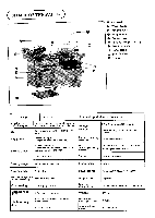
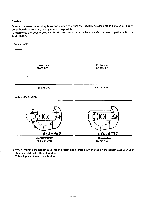
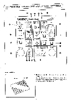
N Installation of the spool stand 1. Loosen screws 0 and remove side cover (S) Q. 2. Install spool stand @ and tighten nut 0 and the cap. 3. Attach side cover (S) Q. t 4 Installation of the control box m eaO a oO o 00 1. Loosen screw 0 and turn panel supporting stud @ to the left. 2. Loosen bolt Q and insert panel supporting stud @ into control box 0 and tighten bolt @. 3. Connect two connectors to control box 0 and tighten screws O. 4. Remove clamping screw 0. 5. Attach a grounding wire and tighten clamping screw O. 6. Secure panel supporting stud @ with screw O. 7. Install pocket bearing CI on control box 0 with screws Q. 0 El Connection of the foot-switch connector 1. Connect connector 0 securely. -6-
-
 1
1 -
2
-
3
-
 4
4 -
 5
5 -
 6
6 -
 7
7 -
 8
8 -
 9
9 -
 10
10 -
 11
11 -
 12
12 -
 13
13 -
 14
14 -
15
-
16
-
17
-
18
-
19
-
20
-
21
-
22
-
23
-
24
-
25
-
26
-
27
-
28
-
29
-
30
-
31
-
32
-
33
-
34
-
35
-
36
-
37
-
38
-
39
-
40
-
41
-
42
-
43
-
44
-
45
-
46
-
47
-
48
-
49
-
50
-
51
-
52
-
53
-
54
-
55
-
56
 |
 |

N
Installation
of
the
spool
stand
1.
Loosen
screws
0
and
remove
side
cover
(S)
Q.
2.
Install
spool
stand
@
and
tighten
nut
0
and
the
cap.
3.
Attach
side
cover
(S)
Q.
t
4
1.
2.
Loosen
screw
0
and
turn
panel
supporting
stud
@
to
the
left.
Loosen
bolt
Q
and
insert
panel
supporting
stud
@
into
control
box
0
and
tighten
bolt
@
.
Installation
of
the
control
box
m
a
o
O
eaO
o
3.
Connect
two
connectors
to
control
box
0
and
tighten
screws
O.
4.
Remove
clamping
screw
0.
5.
Attach
a
grounding
wire
and
tighten
clamping
screw
O.
00
6.
Secure
panel
supporting
stud
@
with
screw
O.
7.
Install
pocket
bearing
CI
on
control
box
0
with
screws
Q.
0
El
Connection
of
the
foot
-switch
connector
1.
Connect
connector
0
securely.
—6—