Cisco 1760 Hardware Installation Guide
Cisco 1760 - VPN Bundle Router Manual
 |
UPC - 746320684857
View all Cisco 1760 manuals
Add to My Manuals
Save this manual to your list of manuals |
Cisco 1760 manual content summary:
- Cisco 1760 | Hardware Installation Guide - Page 1
Cisco 1760 Modular Access Router Hardware Installation Guide Corporate Headquarters Cisco Systems, Inc. 170 West Tasman Drive San Jose, CA 95134-1706 USA http://www.cisco.com Tel: 408 526-4000 800 553-NETS (6387) Fax: 408 526-4100 Customer Order Number: DOC-7813342= Text Part Number: 78-13342-03 - Cisco 1760 | Hardware Installation Guide - Page 2
energy. If it is not installed in accordance with Cisco's installation instructions, it may cause interference with radio and television reception. This equipment has been tested and found to comply with the limits for a Class B digital device in accordance with the specifications in part 15 of the - Cisco 1760 | Hardware Installation Guide - Page 3
document or Website are the property of their respective owners. The use of the word partner does not imply a partnership relationship between Cisco and any other company. (0502R) Cisco 1760 Modular Access Router Hardware Installation Guide Copyright © 2005, Cisco Systems, Inc. All rights reserved. - Cisco 1760 | Hardware Installation Guide - Page 4
- Cisco 1760 | Hardware Installation Guide - Page 5
Technical Support Website xxvi Submitting a Service Request xxvi Definitions of Service Request Severity xxvii Obtaining Additional Publications and Information xxviii Cisco 1760 Router Overview 1-1 Key Features 1-2 Ports and LEDs 1-3 Cisco 1760 Modular Access Router Hardware Installation Guide vii - Cisco 1760 | Hardware Installation Guide - Page 6
Connecting Power to the Router 2-11 Verifying the Installation 2-12 Optional Installation Steps 2-13 Connecting a PC 2-13 Connecting a Modem 2-14 Troubleshooting 3-1 Contacting Your Cisco Reseller 3-1 Recovering a Lost Password 3-2 Cisco 1760 Modular Access Router Hardware Installation Guide viii - Cisco 1760 | Hardware Installation Guide - Page 7
BRI Card B-5 Installing and Upgrading Memory and Packet Voice Data Modules C-1 Safety Information C-1 Opening the Chassis C-3 Locating Modules C-4 Installing a DIMM C-4 Installing a SIMM C-6 Installing a PVDM C-7 Closing the Chassis C-10 Cisco 1760 Modular Access Router Hardware Installation Guide - Cisco 1760 | Hardware Installation Guide - Page 8
Chassis D-9 Installing the Echo Canceler Expansion Modules on Cisco Interface Cards E-1 Multiflex Trunk Interface Cards E-1 Echo E-2 Echo Canceler Expansion Modules E-2 Installing and Configuring the Echo Canceler Expansion Modules E-3 Cisco 1760 Modular Access Router Hardware Installation Guide - Cisco 1760 | Hardware Installation Guide - Page 9
the router features, LEDs, and connectors. • Chapter 2, "Installation," describes how to install the router by connecting cables and power, and tells how to install WAN interface cards (WICs) and voice interface cards (VICs). 78-13342-03 Cisco 1760 Modular Access Router Hardware Installation Guide - Cisco 1760 | Hardware Installation Guide - Page 10
Your Cisco 1760 Modular Access Router, which came with your router, explains how to install voice hardware and how to configure the router for a Voice-over-IP (VoIP) network. • Cisco 1700 Router Software Configuration Guide describes some common network scenarios and how to use the Cisco IOS command - Cisco 1760 | Hardware Installation Guide - Page 11
Conventions • Cisco WAN Interface Cards Hardware Installation Guide describes how to install and configure the WICs and VICs that are supported by the Cisco 1760 router. • Cisco IOS command reference and configuration guides provide complete information about all Cisco IOS CLI commands and how - Cisco 1760 | Hardware Installation Guide - Page 12
that accompanied this device. Statement 1071 SAVE THESE INSTRUCTIONS Waarschuwing BELANGRIJKE VEILIGHEIDSINSTRUCTIES Dit waarschuwingssymbool betekent gevaar. U verkeert lausuntonumeroiden avulla. SÄILYTÄ NÄMÄ OHJEET Cisco 1760 Modular Access Router Hardware Installation Guide xiv 78-13342-03 - Cisco 1760 | Hardware Installation Guide - Page 13
é traduites qui accompagnent cet appareil, référez-vous au numéro de l'instruction situé à la fin de chaque avertissement. CONSERVEZ CES INFORMATIONS Warnung WICHTIGE in questo documento. CONSERVARE QUESTE ISTRUZIONI 78-13342-03 Cisco 1760 Modular Access Router Hardware Installation Guide xv - Cisco 1760 | Hardware Installation Guide - Page 14
de cada advertencia encontrará el número que le ayudará a encontrar el texto traducido en el apartado de traducciones que acompaña a este dispositivo. GUARDE ESTAS INSTRUCCIONES Cisco 1760 Modular Access Router Hardware Installation Guide xvi 78-13342-03 - Cisco 1760 | Hardware Installation Guide - Page 15
som finns i slutet av varje varning för att hitta dess översättning i de översatta säkerhetsvarningar som medföljer denna anordning. SPARA DESSA ANVISNINGAR 78-13342-03 Cisco 1760 Modular Access Router Hardware Installation Guide xvii - Cisco 1760 | Hardware Installation Guide - Page 16
da declaração fornecido ao final de cada aviso para localizar sua tradução nos avisos de segurança traduzidos que acompanham o dispositivo. GUARDE ESTAS INSTRUÇÕES xviii Cisco 1760 Modular Access Router Hardware Installation Guide 78-13342-03 - Cisco 1760 | Hardware Installation Guide - Page 17
. Brug erklæringsnummeret efter hver advarsel for at finde oversættelsen i de oversatte advarsler, der fulgte med denne enhed. GEM DISSE ANVISNINGER 78-13342-03 Cisco 1760 Modular Access Router Hardware Installation Guide xix - Cisco 1760 | Hardware Installation Guide - Page 18
Conventions Preface Cisco 1760 Modular Access Router Hardware Installation Guide xx 78-13342-03 - Cisco 1760 | Hardware Installation Guide - Page 19
Preface Conventions 78-13342-03 Cisco 1760 Modular Access Router Hardware Installation Guide xxi - Cisco 1760 | Hardware Installation Guide - Page 20
literature are available on Cisco.com. Cisco also provides several ways to obtain technical assistance and other technical resources. These sections explain how to obtain technical information from Cisco Systems. xxii Cisco 1760 Modular Access Router Hardware Installation Guide 78-13342-03 - Cisco 1760 | Hardware Installation Guide - Page 21
/pdi.htm You can order Cisco documentation in these ways: • Registered Cisco.com users (Cisco direct customers) can order Cisco product documentation from the Ordering tool: http://www.cisco.com/en/US/partner/ordering/ 78-13342-03 Cisco 1760 Modular Access Router Hardware Installation Guide xxiii - Cisco 1760 | Hardware Installation Guide - Page 22
cisco.com. You can submit comments by using the response card access a Product Security Incident Response Team Really Simple Syndication (PSIRT RSS) feed from this URL: http://www.cisco.com/en/US/products/products_psirt_rss_feed.html xxiv Cisco 1760 Modular Access Router Hardware Installation Guide - Cisco 1760 | Hardware Installation Guide - Page 23
on Cisco.com features extensive online support resources. In addition, Cisco Technical Assistance Center (TAC) engineers provide telephone support. If you do not hold a valid Cisco service contract, contact your reseller. 78-13342-03 Cisco 1760 Modular Access Router Hardware Installation Guide xxv - Cisco 1760 | Hardware Installation Guide - Page 24
your issue is not resolved using the recommended resources, your service request is assigned to a Cisco TAC engineer. The TAC Service Request Tool is located at this URL: http://www.cisco.com/techsupport/servicerequest xxvi Cisco 1760 Modular Access Router Hardware Installation Guide 78-13342-03 - Cisco 1760 | Hardware Installation Guide - Page 25
restore service to satisfactory levels. Severity 4 (S4)-You require information or assistance with Cisco product capabilities, installation, or configuration. There is little or no effect on your business operations. 78-13342-03 Cisco 1760 Modular Access Router Hardware Installation Guide xxvii - Cisco 1760 | Hardware Installation Guide - Page 26
by Cisco Systems for engineering professionals involved in designing, developing, and operating public and private internets and intranets. You can access the Internet Protocol Journal at this URL: http://www.cisco.com/ipj xxviii Cisco 1760 Modular Access Router Hardware Installation Guide 78 - Cisco 1760 | Hardware Installation Guide - Page 27
Preface Obtaining Additional Publications and Information • World-class networking training is available from Cisco. You can view current offerings at this URL: http://www.cisco.com/en/US/learning/index.html 78-13342-03 Cisco 1760 Modular Access Router Hardware Installation Guide xxix - Cisco 1760 | Hardware Installation Guide - Page 28
Obtaining Additional Publications and Information Preface Cisco 1760 Modular Access Router Hardware Installation Guide xxx 78-13342-03 - Cisco 1760 | Hardware Installation Guide - Page 29
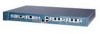
1760 router. Figure 1-1 Cisco 1760 Router 60944 PWR OK PVDM 0 OK PVDM 1 OK MOD OK SLOT0 0 OK 1 SLOT1 0 OK 1 CONSOLE ACT COL FDX 100 LINK 10/100 ETHERNET AUX SLOT2 0 OK 1 SLOT3 0 OK 1 Cisco 1700 Series 78-13342-03 Cisco 1760 Modular Access Router Hardware Installation Guide - Cisco 1760 | Hardware Installation Guide - Page 30
.2 kbps. Supports modem connection to the router, which can be configured and managed from a remote location. Supports up to 115.2 kbps. Supports Simple Network Management Protocol (SNMP) to manage the router over a network. Cisco 1760 Modular Access Router Hardware Installation Guide 1-2 78-13342 - Cisco 1760 | Hardware Installation Guide - Page 31
Card Slot 2 LEDs 8 Auxiliary Port 98 76 9 Ethernet Port 10 Ethernet LEDs 11 Interface Card Slot 1 LEDs 12 Interface Card Slot 0 LEDs 13 MOD OK LED 14 PVDM 0/1 OK LEDs 15 Router OK LED 16 Power LED 60906 78-13342-03 Cisco 1760 Modular Access Router Hardware Installation Guide - Cisco 1760 | Hardware Installation Guide - Page 32
Cards Hardware Installation Guide. Supports a Cisco VIC. For detailed information, refer to the Cisco WAN Interface Cards Hardware Installation Guide. Supports a Cisco VIC. For detailed information, refer to the Cisco WAN Interface Cards Hardware Installation Guide. Cisco 1760 Modular Access Router - Cisco 1760 | Hardware Installation Guide - Page 33
activity on the Ethernet port. Yellow Blinks when there are packet collisions on the local Ethernet network. Green On-Ethernet port is operating in full-duplex mode. Off-Ethernet port is operating in half-duplex mode. 78-13342-03 Cisco 1760 Modular Access Router Hardware Installation Guide 1-5 - Cisco 1760 | Hardware Installation Guide - Page 34
data is being sent to or received from port 0 in slot 0. For the VIC-2BRI-ST-NT/TE, blinks when data is being sent to or received from any of the B channels. VIC-2FXS VIC-2BRI-ST-NT/TE VIC-2DID WIC-1ADSL WIC-1ENET Cisco 1760 Modular Access Router Hardware Installation Guide 1-6 78-13342-03 - Cisco 1760 | Hardware Installation Guide - Page 35
or received from port 1 in slot 0. On when either a WIC or a VIC is correctly inserted in the card slot. On when the first ISDN B channel is connected. Blinks when data is being sent to or received from port 0 in slot 1. 78-13342-03 Cisco 1760 Modular Access Router Hardware Installation Guide 1-7 - Cisco 1760 | Hardware Installation Guide - Page 36
from port 1 in slot 1. On when a VIC is correctly inserted in the card slot. Blinks when data is being sent to or received from port 0 in slot 2. Blinks when data is being sent to or received from port 1 in slot 2. Cisco 1760 Modular Access Router Hardware Installation Guide 1-8 78-13342-03 - Cisco 1760 | Hardware Installation Guide - Page 37
. The router stores a working copy of Cisco IOS software, dynamic configuration information, and routing table information in DRAM. • Nonvolatile RAM (NVRAM)-This type of memory contains the startup configuration. 78-13342-03 Cisco 1760 Modular Access Router Hardware Installation Guide 1-9 - Cisco 1760 | Hardware Installation Guide - Page 38
Cisco IOS software. You can load a new level of the operating system in every router in your network; then, when it is convenient, you can upgrade the whole network to the new level. Amounts of Memory The Cisco 1760 is shipped with 64 MB of DRAM and 32 MB of Flash memory on board. The Cisco 1760 - Cisco 1760 | Hardware Installation Guide - Page 39
the box that your router came in. Table 1-6 Router Box Contents • Power cord (black) • Console cable, RJ-45 to DB-9 (light blue) • Rack-mounting brackets • DB-25 to DB-9 adapter • Cable guide • Product documentation 78-13342-03 Cisco 1760 Modular Access Router Hardware Installation Guide 1-11 - Cisco 1760 | Hardware Installation Guide - Page 40
VIC to a telephone, fax machine, or a telephone wall-jack. You will need one cable for each of these connections. This cable connects the VIC to a PBX trunk line. You will need one cable for each of these connections. 1-12 Cisco 1760 Modular Access Router Hardware Installation Guide 78-13342-03 - Cisco 1760 | Hardware Installation Guide - Page 41
every card. Some ISDN service providers require a Network Termination 1 (NT1) device to connect an ISDN S/T port to the ISDN line. To configure the router from a remote location, connect a modem to the AUX port on the router. 78-13342-03 Cisco 1760 Modular Access Router Hardware Installation Guide - Cisco 1760 | Hardware Installation Guide - Page 42
Additional Required Equipment Chapter 1 Cisco 1760 Router Overview 1-14 Cisco 1760 Modular Access Router Hardware Installation Guide 78-13342-03 - Cisco 1760 | Hardware Installation Guide - Page 43
information in the Regulatory Compliance and Safety Information for Cisco 1700 Routers document that came with your router. Warning Read the installation instructions before you connect the system to its power source. 78-13342-03 Cisco 1760 Modular Access Router Hardware Installation Guide 2-1 - Cisco 1760 | Hardware Installation Guide - Page 44
before mounting or servicing the unit in the rack. The rack-mounting brackets supplied with the router can be attached to a 19- or 24-inch rack. Figure 2-1 shows the bracket mounting points that attach to the rack. Cisco 1760 Modular Access Router Hardware Installation Guide 2-2 78-13342-03 - Cisco 1760 | Hardware Installation Guide - Page 45
rack, use the supplied number-8 Phillips truss-head screws to attach the short side of the bracket to the router. Figure 2-2 shows how to attach the brackets to the two sides of the router with the front panel forward. 78-13342-03 Cisco 1760 Modular Access Router Hardware Installation Guide 2-3 - Cisco 1760 | Hardware Installation Guide - Page 46
PWR OK PVDM 0 OK PVDM 1 OK MOD OK 19" Configuration SLOT 0 OK 0 1 SLOT 1 OK 0 1 60943 Phillips truss-head screws PWR OK PVDM 0 OK PVDM 1 OK MOD OK 24" Configuration SLOT 0 OK 0 1 SLOT 1 OK 0 1 Cisco 1760 Modular Access Router Hardware Installation Guide 2-4 78-13342-03 - Cisco 1760 | Hardware Installation Guide - Page 47
panel of the router and the other devices installed in the rack. If the router is in a 19-inch or 24-inch rack, use the supplied black screw, as shown in Figure 2-4, to attach the cable guide to the left or right bracket. 78-13342-03 Cisco 1760 Modular Access Router Hardware Installation Guide 2-5 - Cisco 1760 | Hardware Installation Guide - Page 48
the Ethernet cable to the yellow ports on the router. Do not connect the cable to an ISDN S/T or U port on a WIC or to an NT1 that is connected to a WIC. Accidentally connecting the cable to the wrong port can damage your router. Cisco 1760 Modular Access Router Hardware Installation Guide 2-6 78 - Cisco 1760 | Hardware Installation Guide - Page 49
1234 5678 3 5X 6X 7X 8X MDI MDI-X 2 60945 1 10/100 Ethernet port 2 Ethernet hub or switch 3 Straight-through Ethernet cable Step 2 Connect the other end of the cable to a network port on the hub or switch. 78-13342-03 Cisco 1760 Modular Access Router Hardware Installation Guide 2-7 - Cisco 1760 | Hardware Installation Guide - Page 50
for installing a WIC or a VIC in the router. Note For details on specific WICs and VICs, on connecting a WIC to the WAN line or VIC to the telephone and fax line, and on configuring the interface with Cisco IOS software, refer to the Cisco WAN Interface Cards Hardware Installation Guide that - Cisco 1760 | Hardware Installation Guide - Page 51
LINK 10/100 ETHERNET AUX SLOT2 0 OK 1 SLOT3 0 OK 1 Cisco 1700 Series 78-13342-03 You should be able to loosen the screws using your fingers; however, if the screws are very tight, you might need to use a Phillips screwdriver. Cisco 1760 Modular Access Router Hardware Installation Guide 2-9 - Cisco 1760 | Hardware Installation Guide - Page 52
with the router. Note Slots 2 and 3 accept VICs only. These slots have a small metal tab on the right side that interferes with a similar tab on WICs, preventing WICs from being inserted by mistake. Step 6 Tighten the screws. 2-10 Cisco 1760 Modular Access Router Hardware Installation Guide 78 - Cisco 1760 | Hardware Installation Guide - Page 53
the host to earth ground during normal use. Follow these steps to connect power to the router and to turn the router on: Step 1 Connect the separate power cord to the power socket on the rear panel. (See Figure 2-8.) 78-13342-03 Cisco 1760 Modular Access Router Hardware Installation Guide 2-11 - Cisco 1760 | Hardware Installation Guide - Page 54
to the router. • OK-On when the router software is loaded and functional. Blinking means that the router is performing a power-on self-test (POST). • ETH ACT-Blinking when there is network traffic on the local Ethernet LAN. 2-12 Cisco 1760 Modular Access Router Hardware Installation Guide 78 - Cisco 1760 | Hardware Installation Guide - Page 55
Cisco IOS software. Follow these steps to connect the router to a terminal or PC: Step 1 Connect the end of the light blue console cable with the RJ-45 connector to the blue console port on the router, as shown in Figure 2-9. 78-13342-03 Cisco 1760 Modular Access Router Hardware Installation Guide - Cisco 1760 | Hardware Installation Guide - Page 56
45 cable, along with an RJ-45-to-DB-25 adapter that you must provide. Follow these steps to connect a modem to the router: Step 1 Connect the RJ-45 end of the console cable to the black AUX port on the router. (See Figure 2-10.) 2-14 Cisco 1760 Modular Access Router Hardware Installation Guide 78 - Cisco 1760 | Hardware Installation Guide - Page 57
4 3 1 Aux port (RJ-45) 2 Modem 3 DB-9-to-DB-25 adapter 4 Console cable Step 2 Connect the DB-9-to-DB-25 adapter to the DB-9 end of the console cable. Step 3 Connect the DB-25 end of the adapter to the modem. 78-13342-03 Cisco 1760 Modular Access Router Hardware Installation Guide 2-15 - Cisco 1760 | Hardware Installation Guide - Page 58
Optional Installation Steps Chapter 2 Installation 2-16 Cisco 1760 Modular Access Router Hardware Installation Guide 78-13342-03 - Cisco 1760 | Hardware Installation Guide - Page 59
IOS release installed on your router • Date you received the router • Brief description of the problem • Brief description of the steps you have taken to isolate the problem • Output from the show tech-support EXEC command 78-13342-03 Cisco 1760 Modular Access Router Hardware Installation Guide - Cisco 1760 | Hardware Installation Guide - Page 60
2, "Installation." Configure the terminal to operate at 9600 baud, 8 data bits, no parity, 1 stop bit and no flow control. Reboot the router by pressing the power switch to the off ( 0 ) position and then to the on ( | ) position. Cisco 1760 Modular Access Router Hardware Installation Guide 3-2 78 - Cisco 1760 | Hardware Installation Guide - Page 61
processor board System flash partition 1 (Read/Write) 8192K bytes of processor board System flash partition 2 (Read/Write) Configuration register is 0x0 Record the setting of the configuration register. It is usually 0x0. 78-13342-03 Cisco 1760 Modular Access Router Hardware Installation Guide 3-3 - Cisco 1760 | Hardware Installation Guide - Page 62
the router by entering the reset command: rommon 2> reset The router resets, and the configuration register is set to 0x142. The router boots the system image in Flash memory and displays the following: --- System Configuration Dialog --- Cisco 1760 Modular Access Router Hardware Installation Guide - Cisco 1760 | Hardware Installation Guide - Page 63
resetting an enable secret password, you will not see it displayed in the show startup-config command output. Complete the password recovery process by performing the steps in the "Resetting the Password" section, which follows. 78-13342-03 Cisco 1760 Modular Access Router Hardware Installation - Cisco 1760 | Hardware Installation Guide - Page 64
to enter configuration mode: Router# configure terminal Enter the config-register command and the original configuration register value that you recorded in Step 5 in the "Determining the Configuration Register Value" section on page 3-2. Cisco 1760 Modular Access Router Hardware Installation Guide - Cisco 1760 | Hardware Installation Guide - Page 65
(described in Table 3-1), depending on the problem. A pattern is a specific number of blinks that is repeated until the router is turned off. If the router experiences any of these problems, contact your Cisco reseller. 78-13342-03 Cisco 1760 Modular Access Router Hardware Installation Guide 3-7 - Cisco 1760 | Hardware Installation Guide - Page 66
FF FF FF FF FF FF 0x70: FF FF FF FF FF FF FF FF FF FF FF FF FF FF FF FF Packet Voice DSP Module Slot 0: Hardware Revision : 2.2 Part Number : 73-3815-01 Board Revision : A0 Cisco 1760 Modular Access Router Hardware Installation Guide 3-8 78-13342-03 - Cisco 1760 | Hardware Installation Guide - Page 67
format version 1 EEPROM contents (hex): 0x20: 01 12 01 00 01 0D 84 08 50 0C 6D 01 00 00 00 00 0x30: 58 00 00 00 00 01 03 00 FF FF FF FF FF FF FF FF WIC/VIC Slot 1: Dual FXS Voice Interface Card Hardware revision 1.1 Board revision F0 Cisco 1760 Modular Access Router Hardware Installation Guide - Cisco 1760 | Hardware Installation Guide - Page 68
27 00 FF FF FF FF FF FF FF FF The show diag command displays similar information for each port available on the router. Table 3-2 lists problems that could occur with the WICs and VICs and describes possible solutions. 3-10 Cisco 1760 Modular Access Router Hardware Installation Guide 78-13342-03 - Cisco 1760 | Hardware Installation Guide - Page 69
following: - 9600 baud - 8 data bits - no parity - 1 stop bit - no flow control Router does not boot or reset There might be an electrical short. Turn off the router immediately. after the WIC or VIC is inserted. 78-13342-03 Cisco 1760 Modular Access Router Hardware Installation Guide 3-11 - Cisco 1760 | Hardware Installation Guide - Page 70
. • Confirm that the Cisco IOS release installed in the router supports the WIC or VIC. The Cisco WAN Interface Cards Hardware Installation Guide lists the software requirements for each card. Router powers on and boots only There might be a problem with the WIC or VIC cables. Consult your when - Cisco 1760 | Hardware Installation Guide - Page 71
central office switch. Do this for each ISDN port installed in the router: Router# clear controller bri0 Router# clear controller bri1 Table 3-4 lists troubleshooting methods for ISDN-specific problems that might occur. 78-13342-03 Cisco 1760 Modular Access Router Hardware Installation Guide 3-13 - Cisco 1760 | Hardware Installation Guide - Page 72
ISDN service provider. If no, the NT1 might be malfunctioning. If no, the router/WIC might be malfunctioning. Contact your Cisco reseller. If yes, the ISDN line might be malfunctioning. Check with your ISDN service provider. 3-14 Cisco 1760 Modular Access Router Hardware Installation Guide 78 - Cisco 1760 | Hardware Installation Guide - Page 73
the router protocol does Layer 3 status say "1 configurations. Active Layer 3 call"? Fan Behavior The fans in the Cisco 1760 router are always on. They are not thermostatically controlled, but they are normally operational. 78-13342-03 Cisco 1760 Modular Access Router Hardware Installation Guide - Cisco 1760 | Hardware Installation Guide - Page 74
Problem-Solving Chapter 3 Troubleshooting 3-16 Cisco 1760 Modular Access Router Hardware Installation Guide 78-13342-03 - Cisco 1760 | Hardware Installation Guide - Page 75
the Cisco 1760 router. Table A-1 Router Specifications Description Specification Console port RJ-45. Auxiliary port RJ-45. Ethernet port RJ-45. Dimensions H x W x D 1.7 x 17.5 x 12.8 in. (4.32 x 44.45 x 32.51 cm). Weight Weight (no WICs, VICs, 8.2 lb (3.7 kg). PVDMs, VPN, SIMM, or DRAM - Cisco 1760 | Hardware Installation Guide - Page 76
Table A-1 Router Specifications (continued) Description Operating Specifications Operating temperature Storage temperature Operating humidity Specification 32 to 104°F (0 to 40°C). -40 to 149°F (-40 to 65°C). 10% to 85%, noncondensing. Cisco 1760 Modular Access Router Hardware Installation Guide - Cisco 1760 | Hardware Installation Guide - Page 77
to connect the router to your local Ethernet network. A 10/100BASE-TX router, such as the Cisco 1760 router, requires Category 5 twisted-pair cable. Table B-1 describes the pinouts for an RJ-45-to-RJ-45 Ethernet cable. 78-13342-03 Cisco 1760 Modular Access Router Hardware Installation Guide B-1 - Cisco 1760 | Hardware Installation Guide - Page 78
equipment. Table B-2 Ethernet Cabling Guidelines Specification 10BASE-T 100BASE-TX Cable type required Category 3, 4, or 5 Category 5 1. Hop count = routing metric used to measure the distance between a source and a destination. Cisco 1760 Modular Access Router Hardware Installation Guide - Cisco 1760 | Hardware Installation Guide - Page 79
-11 modular telephone cable to connect FXS VIC ports (gray) to a telephone or fax machine. • Standard RJ-11 modular telephone cable to connect FXO VIC ports (pink) to the PSTN or to a PBX that does not support E&M signaling. 78-13342-03 Cisco 1760 Modular Access Router Hardware Installation Guide - Cisco 1760 | Hardware Installation Guide - Page 80
line. The cable wiring depends on the PBX type and connection. For details, refer to the Cisco WAN Interface Cards Hardware Installation Guide. Figure B-1 shows how to connect the VICs to the network. Figure B-1 Connecting VICs to the Network FXS VIC VIC FXS 1 SEE MANUAL BEFORE INSTALLATION 0 IN - Cisco 1760 | Hardware Installation Guide - Page 81
other device. Note When an interface configured as network termination (NT) is connecting to a terminal equipment (TE) device, the cable must have the transmit and receive pins swapped (crossover cable). (See Table B-6.) 78-13342-03 Cisco 1760 Modular Access Router Hardware Installation Guide B-5 - Cisco 1760 | Hardware Installation Guide - Page 82
Pin Numbers and Functions ISDN BRI NT/TE Pin 3/T+ Pin 4/R+ Pin 5/R- Pin 6/T- NT Interface (straight-through cable) Pin 3/R+ Pin 4/T+ Pin 5/T- Pin 6/R- TE Interface (crossover cable) Pin 3/T+ Pin 4/R+ Pin 5/R- Pin 6/T- Cisco 1760 Modular Access Router Hardware Installation Guide B-6 78-13342-03 - Cisco 1760 | Hardware Installation Guide - Page 83
section contains safety information that you should read before installing or upgrading memory in the router. Warning Before working on a system that has an on/off switch, turn off the power and unplug the power cord. 78-13342-03 Cisco 1760 Modular Access Router Hardware Installation Guide C-1 - Cisco 1760 | Hardware Installation Guide - Page 84
away from the router first. Warning During this procedure, wear grounding wrist straps to avoid ESD damage to the router. Do not directly touch the backplane with your hand or any metal tool, or you could shock yourself. Cisco 1760 Modular Access Router Hardware Installation Guide C-2 78-13342 - Cisco 1760 | Hardware Installation Guide - Page 85
3 Chassis screw Gently slide the top cover of the router toward you, as shown in Figure C-2. Figure C-2 Removing the Top Cover of the Router 60957 1.5 M150A00X--6/2104.50HAVz~MAX Pull the top cover off in this direction. 78-13342-03 Cisco 1760 Modular Access Router Hardware Installation Guide - Cisco 1760 | Hardware Installation Guide - Page 86
shows where to install a dual in-line DRAM memory module (DIMM), a single inline Flash memory module (SIMM) and packet voice data modules (PVDMs) on the motherboard. Figure C-3 Cisco 1760 Motherboard-Module Locations Fans DIMM slot SIMM slot PVDM slot 1 PVDM slot 0 VPN module Power supply 60958 - Cisco 1760 | Hardware Installation Guide - Page 87
slot, making sure that the notches on the edge of the DIMM are inserted over the bars inside the DIMM slot. Caution Handle DIMMs by the card edges only. DIMMs are ESD-sensitive components and can be damaged by mishandling. 78-13342-03 Cisco 1760 Modular Access Router Hardware Installation Guide - Cisco 1760 | Hardware Installation Guide - Page 88
the rear of the router, and insert it into the slot (see Figure C-5). Rock it into its vertical position, using the minimum force necessary. When the SIMM is properly seated, the connector springs will click into place. Cisco 1760 Modular Access Router Hardware Installation Guide C-6 78-13342-03 - Cisco 1760 | Hardware Installation Guide - Page 89
VIC used with the Cisco 1760 router has two voice ports and requires a single DSP. The 2-port ISDN Voice-BRI requires two DSPs. Table C-1 shows the possible combinations of PVDMs and voice ports for the Cisco 1760 router. 78-13342-03 Cisco 1760 Modular Access Router Hardware Installation Guide C-7 - Cisco 1760 | Hardware Installation Guide - Page 90
any metal tool, or you could shock yourself. Step 1 Step 2 Locate the PVDM slots on the motherboard. (See Figure C-3.) Remove any existing PVDM modules by pulling the PVDM snaps away from the module. (See Figure C-6.) Cisco 1760 Modular Access Router Hardware Installation Guide C-8 78-13342-03 - Cisco 1760 | Hardware Installation Guide - Page 91
Holding the module firmly in the slot, rotate it toward the rear of the router, until you hear a clicking sound and the module is firmly seated in the slot. Make sure that the snaps on both ends of the PVDM are engaged. 78-13342-03 Cisco 1760 Modular Access Router Hardware Installation Guide C-9 - Cisco 1760 | Hardware Installation Guide - Page 92
that shown in Figure C-2, "Removing the Top Cover of the Router," on page C-3. Replace the screws that you removed when you opened the chassis. (See Figure C-1, "Removing the Cisco 1760 Chassis Screws," on page C-3.) C-10 Cisco 1760 Modular Access Router Hardware Installation Guide 78-13342-03 - Cisco 1760 | Hardware Installation Guide - Page 93
the VPN module. Read this section before installing the VPN module in a Cisco 1760 router. VPN Module Parts These parts are needed for installation and are included with the VPN module: • Two metal standoffs • Four screws 78-13342-03 Cisco 1760 Modular Access Router Hardware Installation Guide D-1 - Cisco 1760 | Hardware Installation Guide - Page 94
is connected to power lines, remove jewelry (including rings, necklaces, and watches). Metal objects will heat up when connected to power and ground and can cause serious burns or weld the metal object to the terminals. Cisco 1760 Modular Access Router Hardware Installation Guide D-2 78-13342-03 - Cisco 1760 | Hardware Installation Guide - Page 95
the components, traces, or any connector pins. • Place a removed card component on an antistatic surface or in a static shielding bag. • Do not remove the wrist or ankle strap until after you complete the installation. 78-13342-03 Cisco 1760 Modular Access Router Hardware Installation Guide D-3 - Cisco 1760 | Hardware Installation Guide - Page 96
the screws that hold the top and bottom of the chassis together, as shown in Figure D-1. Note Some Cisco 1760 routers have five chassis screws in the rear assembly, but most models have three screws in the rear assembly. Cisco 1760 Modular Access Router Hardware Installation Guide D-4 78-13342-03 - Cisco 1760 | Hardware Installation Guide - Page 97
Figure D-2 Removing the Top Cover of the Router 60957 1.5 M150A00X--6/2104.50HAVz~MAX Pull the top cover off in this direction. Step 4 Place the router bottom on an antistatic mat, and begin installing the VPN module. 78-13342-03 Cisco 1760 Modular Access Router Hardware Installation Guide D-5 - Cisco 1760 | Hardware Installation Guide - Page 98
module. Step 1 Install the two standoffs on the module, as shown in Figure D-3. Figure D-3 Installing the Standoffs on the VPN Module Screw Standoff Screw Standoff is installed into the hole just behind the large connector. 46084 Cisco 1760 Modular Access Router Hardware Installation Guide - Cisco 1760 | Hardware Installation Guide - Page 99
socket. Figure D-5 Seating the VPN Module 60954 PWR OK PVDM 0 OK PVDM 1 OK MOD OK SLOT0 0 OK 1 SLOT1 0 OK 1 CONSOLE ACT COL FDX 100 LINK 10/100 ETHERNET AUX SLOT2 0 OK 1 SLOT3 0 OK 1 Cisco 1700 Series 78-13342-03 Cisco 1760 Modular Access Router Hardware Installation Guide D-7 - Cisco 1760 | Hardware Installation Guide - Page 100
Step 4 Turn the chassis over, and attach the standoffs to it by using the screws provided, as shown in Figure D-6. Figure D-6 Securing the Standoff to the Router Motherboard Standoff screws Bottom of the board 45919 Cisco 1760 Modular Access Router Hardware Installation Guide D-8 78-13342-03 - Cisco 1760 | Hardware Installation Guide - Page 101
from that shown in Figure D-2, "Removing the Top Cover of the Router," on page D-5. Replace the screws that you removed when you opened the chassis. (See Figure D-1, "Removing the Cisco 1760 Chassis Screws," on page D-5.) 78-13342-03 Cisco 1760 Modular Access Router Hardware Installation Guide D-9 - Cisco 1760 | Hardware Installation Guide - Page 102
Installing the VPN Module in a Cisco 1760 Router Appendix D Installing the Virtual Private Network Module D-10 Cisco 1760 Modular Access Router Hardware Installation Guide 78-13342-03 - Cisco 1760 | Hardware Installation Guide - Page 103
only support Note For additional information about the Cisco 1- and 2-port T1/E1 multiflex trunk interface cards, refer to the Cisco 1- and 2-port T1/E1 Multiflex Voice/WAN Interface Cards for the Cisco 1751 and 1760 Routers. 78-13342-03 Cisco 1760 Modular Access Router Hardware Installation Guide - Cisco 1760 | Hardware Installation Guide - Page 104
motherboard. By offloading this processing, hardware-based echo cancellation results in more robust echo cancellation. The echo canceler expansion modules enable high performance hardware-based echo cancellation for up to 64 voice calls. Cisco 1760 Modular Access Router Hardware Installation Guide - Cisco 1760 | Hardware Installation Guide - Page 105
on Cisco Interface Cards. For detailed information about configuring 1- and 2-port multiflex trunk interface cards with echo cancellation, refer to T1/E1 Multiflex Voice/WAN Interface Cards with Echo Cancellation Module. 78-13342-03 Cisco 1760 Modular Access Router Hardware Installation Guide E-3 - Cisco 1760 | Hardware Installation Guide - Page 106
Appendix E Cisco 1760 Modular Access Router Hardware Installation Guide E-4 78-13342-03 - Cisco 1760 | Hardware Installation Guide - Page 107
command conventions xxii commands clear controller 3-13 clear interface 3-13 config-register 3-6 configure terminal 3-6 copy 3-5, 3-6 dialer map 3-15 dialer string 3-15 enable 3-5 enable secret 3-6 isdn switch-type 3-15 78-13342-03 Cisco 1760 Modular Access Router Hardware Installation Guide IN - Cisco 1760 | Hardware Installation Guide - Page 108
modules E-1, E-2 enable command 3-5 enable password, recovering 3-2 enable secret command 3-6 enable secret password, resetting 3-6 equipment, additional required 1-12 to 1-13 Ethernet ACT LED 1-5 Ethernet cable connecting 2-6 IN-2 Cisco 1760 Modular Access Router Hardware Installation Guide - Cisco 1760 | Hardware Installation Guide - Page 109
description 1-2 IOS See Flash memory ISDN, troubleshooting 3-13 to 3-15 isdn switch-type command 3-15 L LEDs Ethernet 1-5 front panel 1-3 OK LED diagnostics 3-7 to 3-8 system 1-5 verifying installation 2-12 to 2-13 WIC/VIC 1-6 to 1-9 Cisco 1760 Modular Access Router Hardware Installation Guide IN - Cisco 1760 | Hardware Installation Guide - Page 110
to B-2 FXS and FXO VIC connectors B-4 ports auxiliary 1-3, 2-14, A-1 console 1-2, 1-3, 2-13, A-1 Ethernet 1-2, 1-3, 2-7, A-1 front panel 1-3 power cable 2-11 to 2-12 connecting 2-11 to 2-12 problem solving 3-7 specifications A-1 IN-4 Cisco 1760 Modular Access Router Hardware Installation Guide 78 - Cisco 1760 | Hardware Installation Guide - Page 111
B-6 console cable and adapter B-3 Ethernet B-1 to B-2 VIC cables B-3 to B-5 operating A-2 technical A-1 system LEDs 1-5 T technical specifications A-1 terminal emulation settings 2-13 text conventions xiii troubleshooting 78-13342-03 Cisco 1760 Modular Access Router Hardware Installation Guide IN - Cisco 1760 | Hardware Installation Guide - Page 112
location on router D-7 W WAN interface cards See WICs WIC/VIC LEDs 1-6 to 1-9 slots 1-4 WICs installing 2-8 LEDs 1-6 to 1-9 problem solving 3-7 required 1-12 router slots 1-4 supported cards 1-2 troubleshooting 3-8, 3-11 to 3-12 IN-6 Cisco 1760 Modular Access Router Hardware Installation Guide 78
-
 1
1 -
 2
2 -
 3
3 -
 4
4 -
 5
5 -
 6
6 -
 7
7 -
8
-
9
-
10
-
11
-
12
-
13
-
14
-
15
-
16
-
17
-
18
-
19
-
20
-
21
-
22
-
23
-
24
-
25
-
26
-
27
-
28
-
29
-
30
-
31
-
32
-
33
-
34
-
35
-
36
-
37
-
38
-
39
-
40
-
41
-
42
-
43
-
44
-
45
-
46
-
47
-
48
-
49
-
50
-
51
-
52
-
53
-
54
-
55
-
56
-
57
-
58
-
59
-
60
-
61
-
62
-
63
-
64
-
65
-
66
-
67
-
68
-
69
-
70
-
71
-
72
-
73
-
74
-
75
-
76
-
77
-
78
-
79
-
80
-
81
-
82
-
83
-
84
-
85
-
86
-
87
-
88
-
89
-
90
-
91
-
92
-
93
-
94
-
95
-
96
-
97
-
98
-
99
-
100
-
101
-
102
-
103
-
104
-
105
-
106
-
107
-
108
-
109
-
110
-
111
-
112
 |
 |

Corporate Headquarters
Cisco Systems, Inc.
170 West Tasman Drive
San Jose, CA 95134-1706
USA
Tel:
408 526-4000
800 553-NETS (6387)
Fax:
408 526-4100
Cisco 1760 Modular Access Router
Hardware Installation Guide
Customer Order Number: DOC-7813342=
Text Part Number: 78-13342-03