Cisco 1760 Hardware Installation Guide - Page 107
INDEX, clear interface command
 |
UPC - 746320684857
View all Cisco 1760 manuals
Add to My Manuals
Save this manual to your list of manuals |
Page 107 highlights
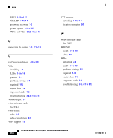
INDEX A accessory kit 1-11 adapter, included 1-11 AutoInstall support 1-3 auxiliary port connecting to a modem 2-14 to 2-15 description 1-2, 1-4 figure 1-3 specification A-1 B brackets attaching to rack 2-5 attaching to router 2-3 to 2-4 rack-mounting 2-2 break, sending to router 3-4 C cable guide attaching 2-5 to 2-6 cables 2-port ISDN BRI card B-5 console B-3 Ethernet 2-6, B-1 included with router 1-11 required 1-12 to 1-13 specifications B-1 to B-6 VIC B-3 to B-4 caution, definition xiii chassis closing C-10, D-9 dimensions A-1 opening C-3, D-4 to D-5 clear controller command 3-13 clear interface command 3-13 command conventions xxii commands clear controller 3-13 clear interface 3-13 config-register 3-6 configure terminal 3-6 copy 3-5, 3-6 dialer map 3-15 dialer string 3-15 enable 3-5 enable secret 3-6 isdn switch-type 3-15 78-13342-03 Cisco 1760 Modular Access Router Hardware Installation Guide IN-1
-
 1
1 -
2
-
3
-
4
-
5
-
6
-
7
-
8
-
9
-
10
-
11
-
12
-
13
-
14
-
15
-
16
-
17
-
18
-
19
-
20
-
21
-
22
-
23
-
24
-
25
-
26
-
27
-
28
-
29
-
30
-
31
-
32
-
33
-
34
-
35
-
36
-
37
-
38
-
39
-
40
-
41
-
42
-
43
-
44
-
45
-
46
-
47
-
48
-
49
-
50
-
51
-
52
-
53
-
54
-
55
-
56
-
57
-
58
-
59
-
60
-
61
-
62
-
63
-
64
-
65
-
66
-
67
-
68
-
69
-
70
-
71
-
72
-
73
-
74
-
75
-
76
-
77
-
78
-
79
-
80
-
81
-
82
-
83
-
84
-
85
-
86
-
87
-
88
-
89
-
90
-
91
-
92
-
93
-
94
-
95
-
96
-
97
-
98
-
99
-
100
-
101
-
 102
102 -
 103
103 -
 104
104 -
 105
105 -
 106
106 -
 107
107 -
 108
108 -
 109
109 -
 110
110 -
 111
111 -
 112
112
 |
 |