Cisco 1760 Hardware Installation Guide - Page 55
Optional Installation Steps, Connecting a PC - configuration for cable modem
 |
UPC - 746320684857
View all Cisco 1760 manuals
Add to My Manuals
Save this manual to your list of manuals |
Page 55 highlights
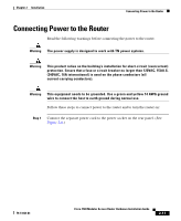
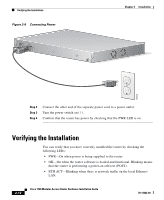
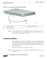
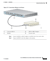
Chapter 2 Installation Optional Installation Steps • SLOT 0 and SLOT 1 OK-On when a WIC or VIC is correctly installed in the slot. • SLOT 2 and SLOT 3 OK-On when a VIC is correctly installed in the slot. • SLOT 0, SLOT 1, SLOT 2, and SLOT 3-Activity on ports 0 and 1 of each of these slots varies, depending on the type of WIC or VIC installed. See Table 1-5 in Chapter 1, "Cisco 1760 Router Overview," for detailed information on activity at different ports. • LINK-On when the router is correctly connected to the local Ethernet LAN through the 10/100-Mbps Ethernet port. Optional Installation Steps This section describes the following installation steps that you might or might not use, depending on your site and how you are configuring the router: • Connecting a PC • Connecting a Modem Connecting a PC If you want to configure the router through the Cisco IOS command-line interface (CLI), you must connect the router console port to a terminal or PC. The cable required for this connection is included with the router. The PC must have some type of terminal emulation software installed. The software should be configured with the following parameters: 9600 baud, 8 data bits, no parity, 1 stop bit, and no flow control. Refer to the Cisco 1700 Router Software Configuration Guide for detailed information about configuring the router using Cisco IOS software. Follow these steps to connect the router to a terminal or PC: Step 1 Connect the end of the light blue console cable with the RJ-45 connector to the blue console port on the router, as shown in Figure 2-9. 78-13342-03 Cisco 1760 Modular Access Router Hardware Installation Guide 2-13
-
 1
1 -
2
-
3
-
4
-
5
-
6
-
7
-
8
-
9
-
10
-
11
-
12
-
13
-
14
-
15
-
16
-
17
-
18
-
19
-
20
-
21
-
22
-
23
-
24
-
25
-
26
-
27
-
28
-
29
-
30
-
31
-
32
-
33
-
34
-
35
-
36
-
37
-
38
-
39
-
40
-
41
-
42
-
43
-
44
-
45
-
46
-
47
-
48
-
49
-
 50
50 -
 51
51 -
 52
52 -
 53
53 -
 54
54 -
 55
55 -
 56
56 -
 57
57 -
 58
58 -
 59
59 -
 60
60 -
61
-
62
-
63
-
64
-
65
-
66
-
67
-
68
-
69
-
70
-
71
-
72
-
73
-
74
-
75
-
76
-
77
-
78
-
79
-
80
-
81
-
82
-
83
-
84
-
85
-
86
-
87
-
88
-
89
-
90
-
91
-
92
-
93
-
94
-
95
-
96
-
97
-
98
-
99
-
100
-
101
-
102
-
103
-
104
-
105
-
106
-
107
-
108
-
109
-
110
-
111
-
112
 |
 |
