Cisco 3825 User Guide - Page 15
Front Panel Description - gateway
 |
UPC - 746320981505
View all Cisco 3825 manuals
Add to My Manuals
Save this manual to your list of manuals |
Page 15 highlights
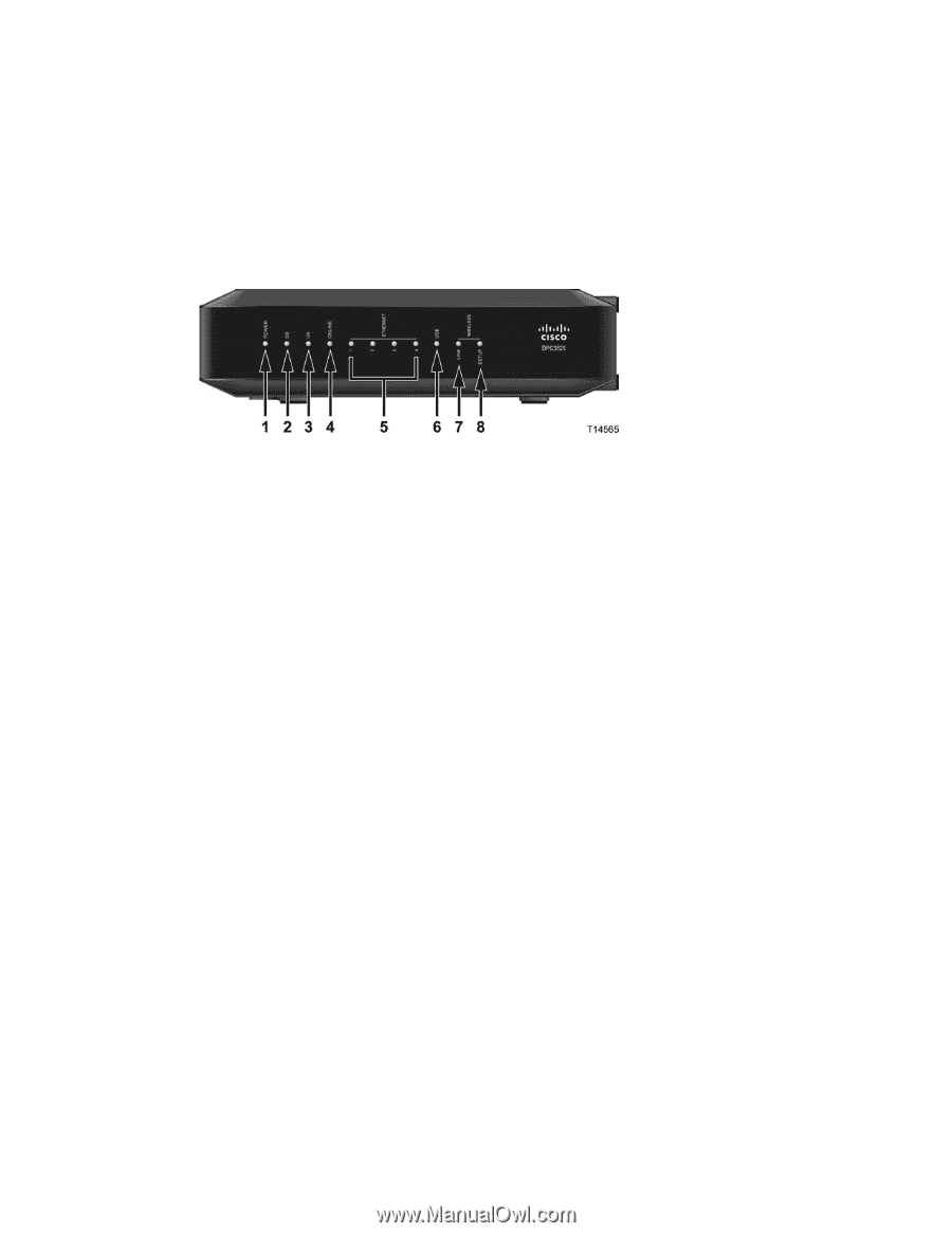
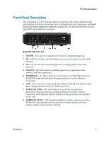
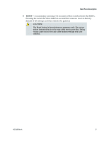
Front Panel Description Front Panel Description The front panel of your residential gateway provides LED status indicators that indicate how well and at what state your residential gateway is operating. See Front Panel LED Status Indicator Functions (on page 96), for more information on front panel LED status indicator functions. Model DPC3825 shown here 1 POWER-ON, power is applied to the wireless residential gateway 2 DS-ON, the wireless residential gateway is receiving data from the cable network 3 US-On, the wireless residential gateway is sending data to the cable network 4 ONLINE-ON, the wireless residential gateway is registered on the network and fully operational 5 ETHERNET 1 - 4-ON, a device is connected to one of the Ethernet ports. BLINKING indicates that data is being transferred over the Ethernet connection 6 USB-ON, a device is connected to the USB port. BLINKING indicates that data is being transferred over the USB connection 7 WIRELESS LINK-ON, the Wireless Access Point is operational. BLINKING indicates that data is being transferred over the wireless connection. OFF indicates that the wireless access point has been disabled by the user 8 WIRELESS SETUP-OFF (normal condition) wireless setup is not active. BLINKING indicates the user has activated wireless setup to add new wireless clients on the wireless network 4021196 Rev A 15
-
 1
1 -
2
-
3
-
4
-
5
-
6
-
7
-
8
-
9
-
 10
10 -
 11
11 -
 12
12 -
 13
13 -
 14
14 -
 15
15 -
 16
16 -
 17
17 -
 18
18 -
 19
19 -
 20
20 -
21
-
22
-
23
-
24
-
25
-
26
-
27
-
28
-
29
-
30
-
31
-
32
-
33
-
34
-
35
-
36
-
37
-
38
-
39
-
40
-
41
-
42
-
43
-
44
-
45
-
46
-
47
-
48
-
49
-
50
-
51
-
52
-
53
-
54
-
55
-
56
-
57
-
58
-
59
-
60
-
61
-
62
-
63
-
64
-
65
-
66
-
67
-
68
-
69
-
70
-
71
-
72
-
73
-
74
-
75
-
76
-
77
-
78
-
79
-
80
-
81
-
82
-
83
-
84
-
85
-
86
-
87
-
88
-
89
-
90
-
91
-
92
-
93
-
94
-
95
-
96
-
97
-
98
-
99
-
100
-
101
-
102
 |
 |